50 Recording & Mixing Techniques
Patching in Signal Processors
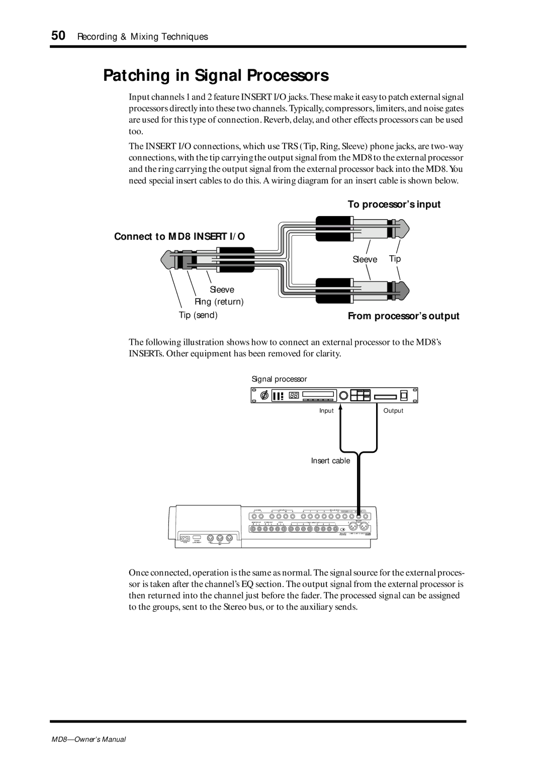
Input channels 1 and 2 feature INSERT I/O jacks. These make it easy to patch external signal processors directly into these two channels. Typically, compressors, limiters, and noise gates are used for this type of connection. Reverb, delay, and other effects processors can be used too.
The INSERT I/O connections, which use TRS (Tip, Ring, Sleeve) phone jacks, are
To processor’s input
Connect to MD8 INSERT I/O
| Sleeve Tip |
Sleeve |
|
Ring (return) |
|
Tip (send) | From processor’s output |
The following illustration shows how to connect an external processor to the MD8’s INSERTs. Other equipment has been removed for clarity.
Signal processor
88
Input ![]() Output
Output
Insert cable
AUX SEND |
| 12 | LINE INPUT |
| 9 | 8 | 7 | 6 | 5 | MIC/LINE INPUT | 2 |
|
| 1 | ||||
2 | 1 |
| 11 | 10 |
| 4 | 3 | INSERT I/O | INSERT I/O | |||||||||
|
|
|
|
|
|
|
|
|
|
|
|
|
|
|
| MIC/LINE |
|
|
MONITOR OUT | STEREO OUT | 2TR IN |
|
|
|
| TRACK DIRECT OUT |
|
|
| 2 |
| IN (BAL) |
| 1 | |||
R | L | R | L | R | L | 8 | 7 | 6 | 5 | 4 | 3 | 2 | 1 |
|
|
|
|
|
|
|
|
|
|
|
|
|
|
|
|
|
|
|
| 2 | 1 | 2 | 1 |
|
|
|
|
|
|
|
|
|
|
|
|
|
|
| 3 |
|
| 3 |
|
|
|
|
|
|
|
|
|
|
|
|
|
| ON OFF | 1: GMD 2: HOT 3: COLD DC48V | |||
|
|
|
|
|
|
|
|
|
|
|
|
|
| PHANTOM |
|
|
| MAX. 7mA |
POWER
AC IN | ON OFF | THRU | OUT | IN |
MID
Once connected, operation is the same as normal. The signal source for the external proces- sor is taken after the channel’s EQ section. The output signal from the external processor is then returned into the channel just before the fader. The processed signal can be assigned to the groups, sent to the Stereo bus, or to the auxiliary sends.