Agilent Technologies 5951-2827, 5951-2826 manual Short On/Off, Transition Times and Slew Rates

Page 29

Short On/Off

A load can simulate a short circuit at its input by turning the load on with full-scale current. The short circuit can be toggled

on/off at the front panel ( key) or via the GPIB (INPUT:SHORT ONOFF command). The short on/off change uses the slew rate setting of the active mode and range.

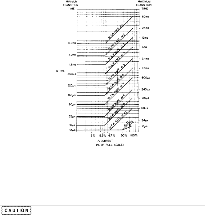
Figure 2-8. Transition Times and Slew Rates

The actual value of the electronic short is dependent on the mode and range that are active when the short is turned on. In CV mode, it is equivalent to programming zero volts. In CC mode, it is equivalent to programming full-scale current for the present CC range. In CR mode, it is equivalent to programming the minimum resistance for the present resistance range.

Note that turning the short on in CV mode may cause the load to draw so much current that the software current limit operates, which may turn the input off.

Turning the short circuit on does not affect the programmed settings, and the input will return to the previously programmed values when the short is turned off.

Pressing the Short on/off key with certain user applications may cause damage to the equipment being tested, which may result in personal injury. Contact your Agilent Sales and Service office if you need to have the Short on/off key disabled.

Operation Overview 29

Image 29
Contents Operating Manual Agilent Part No Microfiche Part No Updated AprilCertification Safety Summary Symbol Description Safety SummaryHerstellerbescheinigung Manufacturer’s DeclarationPrinting History Table of Contents Calibration Local OperationRemote Operation Considerations for Operating in Constant Resistance Mode Reader Path What’s In This ManualOptions General InformationSpecifications Safety RequirementsModes Continuous Mode Regulation Constant Resistance Mode RangesPulsed Mode 6060B 6063BCurrent Readback Temperature Coefficient Supplemental Characteristics 6060B 6063BResolution Bandwidth Maximum Readback CapabilityMaximum VA Peak Inrush Current 2.5 a typical Supplemental CharacteristicsCurrent Slew Rate Rate # High Range Step Low Range Step Transition TimeModel 6063B Range Transient Current Level Resistance Slew RateOvershoot With unit on 6060B 6063B 10%With unit off WidthPage Front Panel Description IntroductionRemote Programming Operation OverviewProgrammable Features Local/Remote ControlConstant Current CC Mode Modes of OperationSoftware Current Limit Triggered Current LevelImmediate Resistance Level Constant Resistance CR ModeSlew Rate Transient Resistance Level Constant Voltage CV ModeTriggered Resistance Level Triggered Voltage Level Immediate Voltage LevelTransient Voltage Level Transient OperationPulsed Transient Operation Hpsl Command DescriptionSelects pulsed transient operation Selects the external trigger inputSets pulse width to 1 millisecond Selects the external trigger input sourceTriggering a transient pulse Triggering a preset levelToggling Slew Rate And Minimum Transition TimeRisetime Transition Limitation Input Current, Voltage, and Power MeasurementTransition Times and Slew Rates Short On/OffReading Remote Programming Errors Saving and Recalling SettingsInput On/Off Status ReportingResetting Latched Protection Protection FeaturesOvervoltage OvercurrentOverpower Control ConnectorOvertemperature Reverse VoltageExternal Programming Input FaultMonitor Outputs Port On/Off Inspection Check Line Voltage Location and CoolingTurn-On Checkout Line Voltage Fuse Agilent Part No Voltage Select SwitchesGpib Errors Input Errors Display Description Connect The Power CordError Turn-On/SelftestController Connection Power TestGpib Connector Wire Size Strip back Rear Panel Connectors and SwitchesGpib Address AWGInput Binding Post Control Connector +S and -S Pins 3IM and VM CommonSense Switch Trigger ConnectorApplication Connections Zero-Volt Loading Connections Maximum Wire Lengths to Limit Voltage DropsParallel Connections 11. Local Sensing 13. Parallel Operation Page Local Operation Front Panel Controls and Indicators DescriptionControls and Indicators Description Function Keys Local Control Overview Turning the Input On/Off Using The Function Keys∙ Short on Recommended Programming Sequence Setting CC Values Setting the Mode of OperationCC Programming Ranges Function Key DisplayExamples Setting CR Values Examples Setting CV Values Function Key Display Range of Values Continuous Pulse Train Programming RangesShorting The Input Using The System KeysDisplaying Error Codes Setting The Electronic Load’s Gpib AddressChanging Wake-up Settings Factory Default Settings Function 6060B 6063BRecalling the Factory Default Values Gpib Address Enter/Output StatementsOutput EnterRemote Programming Commands Sending a Remote CommandGetting Data Back Output 705 MEASCURR?Ranges ModesTransient levels Slew RatesRemote Programming Flowchart Sheet Remote Programming Flowchart Sheet CR Mode Example CC Mode ExampleCV Mode Example Pulsed Transient Operation Example Continuous Transient Operation ExampleOutput 705TRAN on Output 705INPUT on Hpsl Command Short FormRemote Programming Ranges Function Constant Current CC6060B Constant Resistance CRConstant Voltage CV Transient OperationPage Example Programs Equipment Characteristics Recommended ModelEquipment Required Equipment Required for CalibrationCalibration Commands Example Program Calibration FlowchartsCalibration Information 6060B 6063B Supply Shunt Values SettingsCalibration Flowchart Calibration Flowchart Calibration Flowchart Pause Program ListingWait END ifPrint Voltage Calibration Pause SubendElse Line ExplanationPage Considerations For Operating In Constant Resistance Mode Considerations For Operating In Constant Resistance ModeConsiderations For Operating In Constant Resistance Mode Index IndexIndex 24, 25, 26 Index Agilent Sales and Support Office Agilent Sales and Support OfficesManual Updates