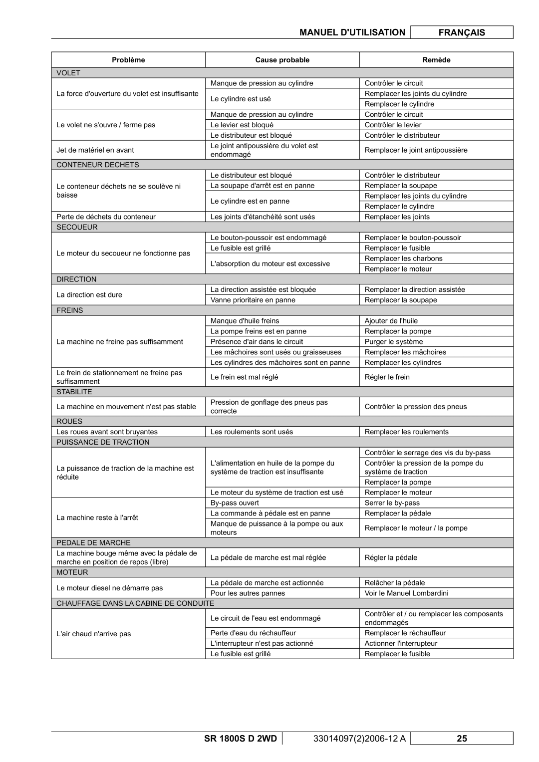
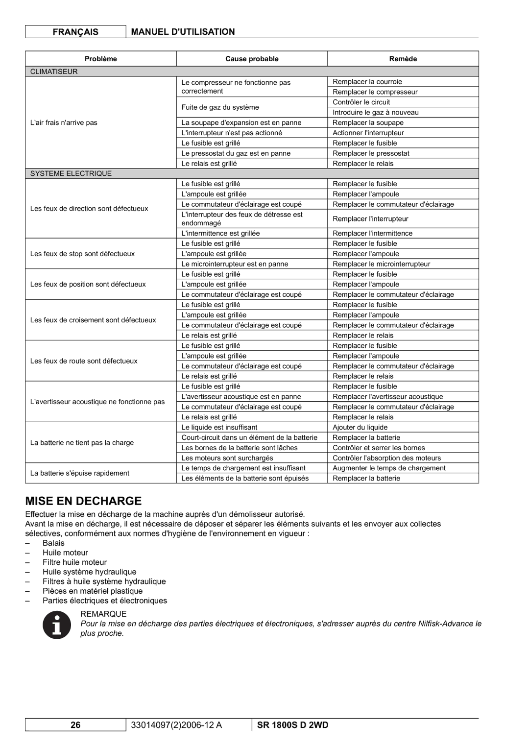
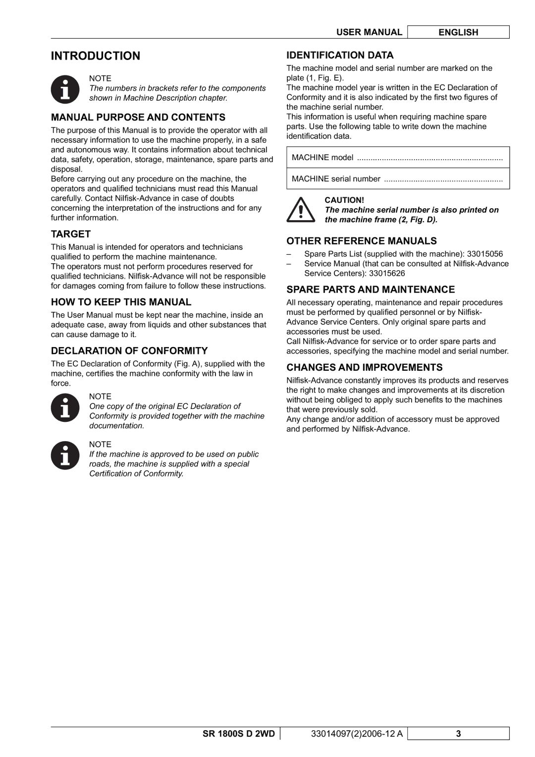
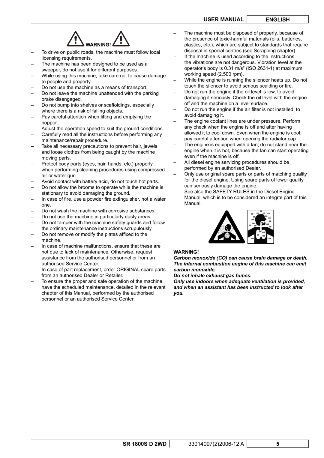
Nilfisk-Advance America SR 1800S 2WD manuel dutilisation Safety, Symbols, General Instructions

Page 58

ENGLISH

USER MANUAL

SAFETY

The following symbols indicate potentially dangerous situations. Always read this information carefully and take all necessary precautions to safeguard people and property. The operator's cooperation is essential in order to prevent injury. No accident prevention program is effective without the total cooperation of the person responsible for the machine operation. Most of the accidents that may occur while working or moving around are caused by failure to comply with the simplest rules for exercising prudence. A careful and prudent operator is the best guarantee against accidents and is essential for successful completion of any prevention program.

SYMBOLS

DANGER!

It indicates a dangerous situation with risk of death for the operator.

WARNING!

It indicates a potential risk of injury for people.

CAUTION!

It indicates a caution or a remark related to important or useful functions.

Pay careful attention to the paragraphs marked by this symbol.

NOTE

It indicates a remark related to important or useful functions.

CONSULTATION

It indicates that it is necessary to consult the User Manual before performing any procedure.

GENERAL INSTRUCTIONS

Specifi c warnings and cautions to inform about potential damages to people and machine are shown below.

DANGER!

This machine must be used by properly trained and authorised personnel only. Moreover, the operator must:

Be of full age

Have a driving licence

Be in normal psycho-physical conditions

Not be under the effect of substances that alters the nervous system (alcohol, psycopharmaceuticals, drugs, etc.)

Remove the ignition key before performing any maintenance/repair procedure.

This machine must be used by properly trained and authorised personnel only. Children or disabled people cannot use this machine.

Do not wear jewels when working near moving parts.

Do not work under the lifted machine without supporting it with safety stands.

Do not operate the machine near toxic, dangerous,

fl ammable and/or explosive powders, liquids or vapours.

Be careful, fuel is highly fl ammable.

Do not smoke or bring naked fl ames in the area where the machine is refuelled or where the fuel is stored.

Refuel outdoors or in a well-ventilated area, with the engine off.

Do not fi ll the fuel tank to the top, but leave at least 4 cm from the fi ller neck to allow the fuel to expand.

After refuelling, check that the fi ller cap is tightly closed.

If any fuel is spilled while refuelling, clean up the affected area and allow the vapours to dissipate before starting the engine.

Avoid contact with skin and do not breathe in fuel vapours. Keep out of reach of children.

Before performing any maintenance/repair procedure remove the ignition key, engage the parking brake and disconnect the battery.

When working under open hoods/lids, make sure that they cannot be closed by accident.

When performing maintenance procedures with the lifted hopper, fi x it with the support rods.

During machine transportation, the fuel tank must not be full.

Diesel engine exhaust gases contain carbon monoxide, an extremely poisonous, colourless, and odourless gas. Do not inhale. Do not keep the engine running in a closed area.

Do not lay any object on the engine.

Before working on the engine turn it off. To prevent the engine from starting accidentally, disconnect the battery negative terminal.

See also the SAFETY RULES in the Diesel Engine Manual, which is to be considered an integral part of this Manual.

4

33014097(2)2006-12 A

SR 1800S D 2WD
Image 58
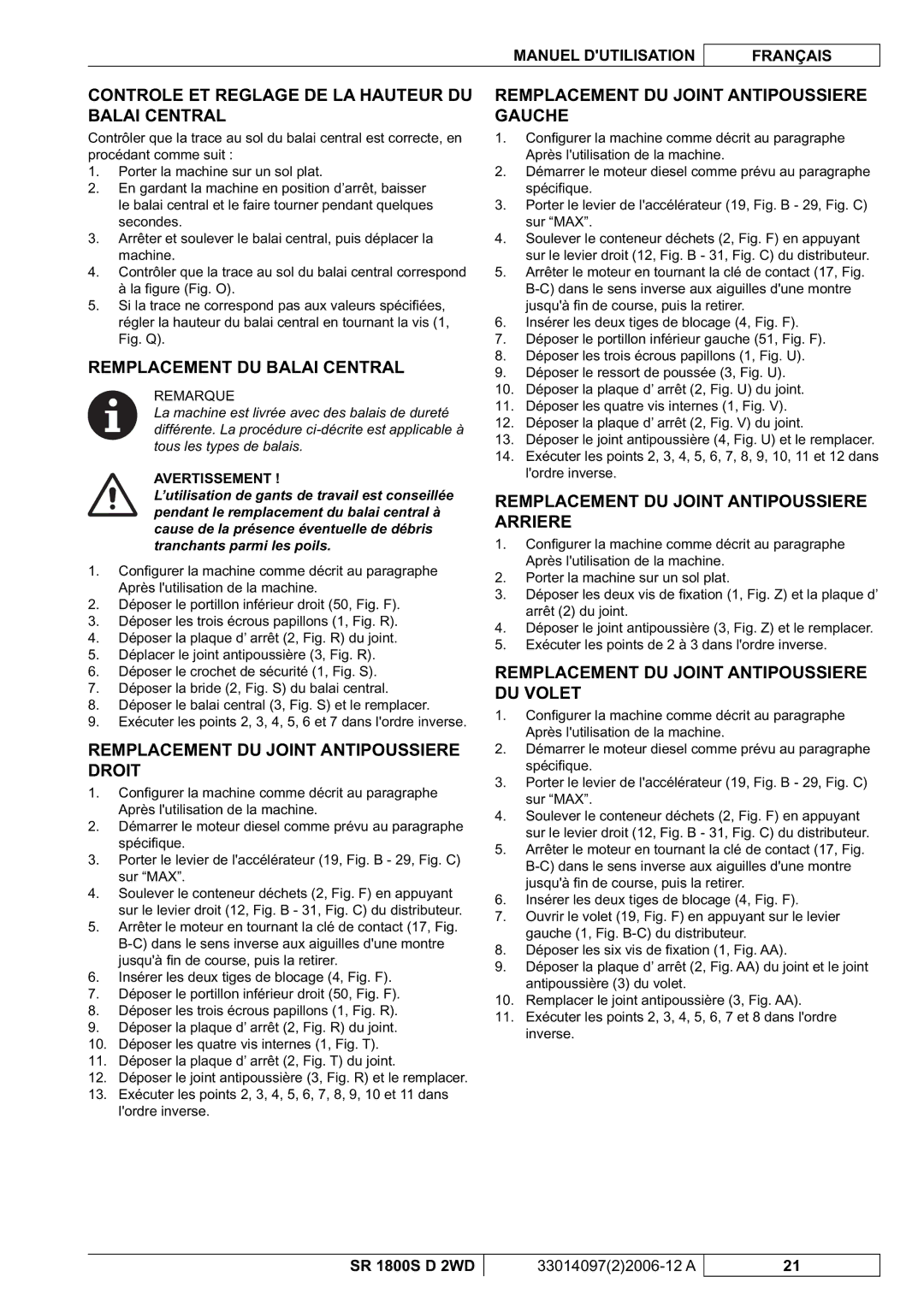
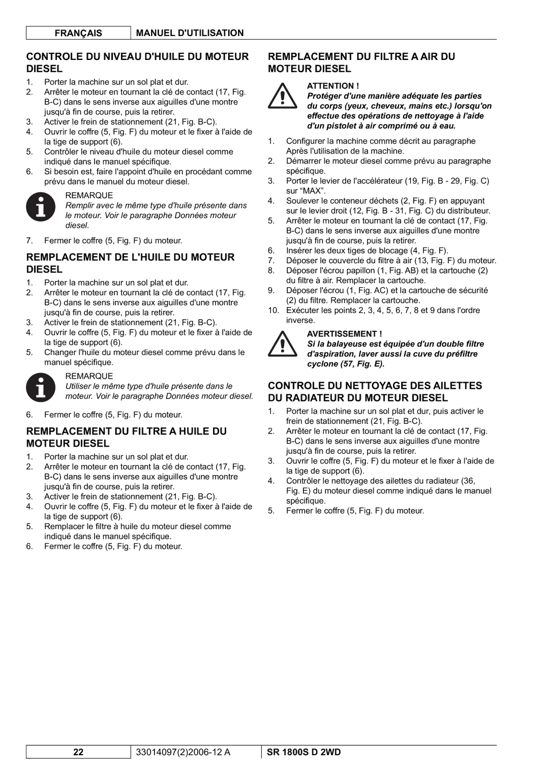
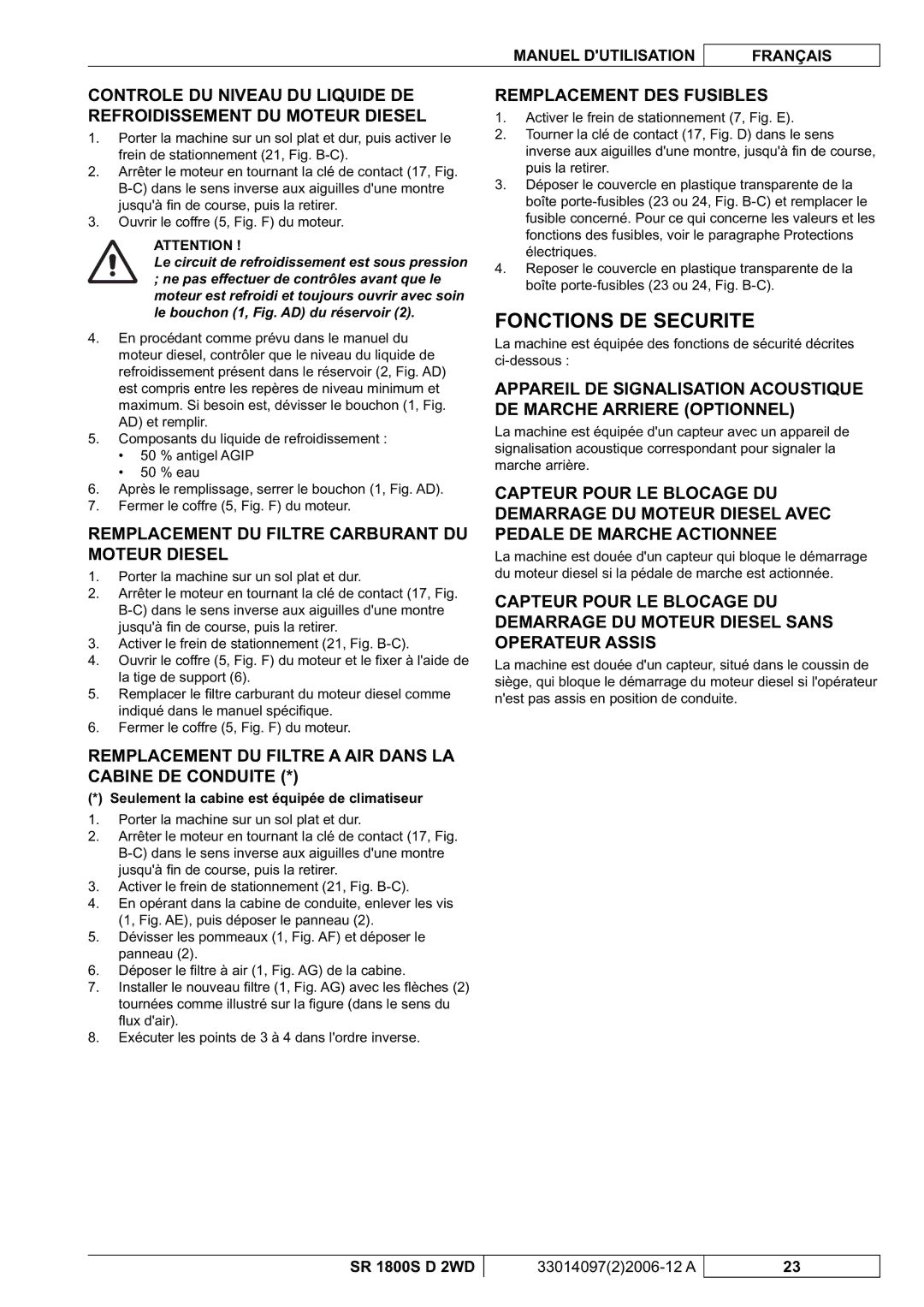
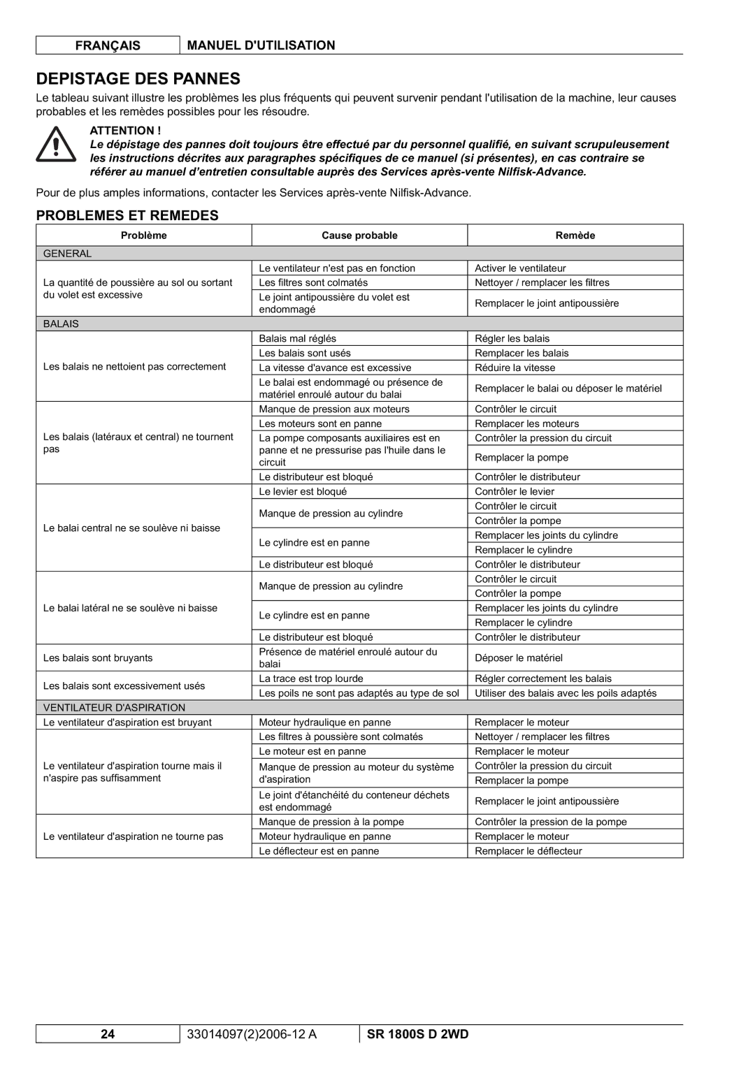
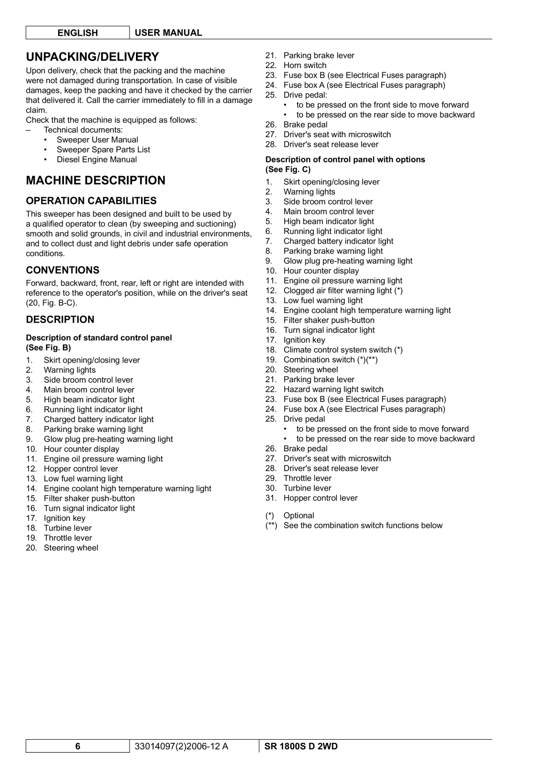
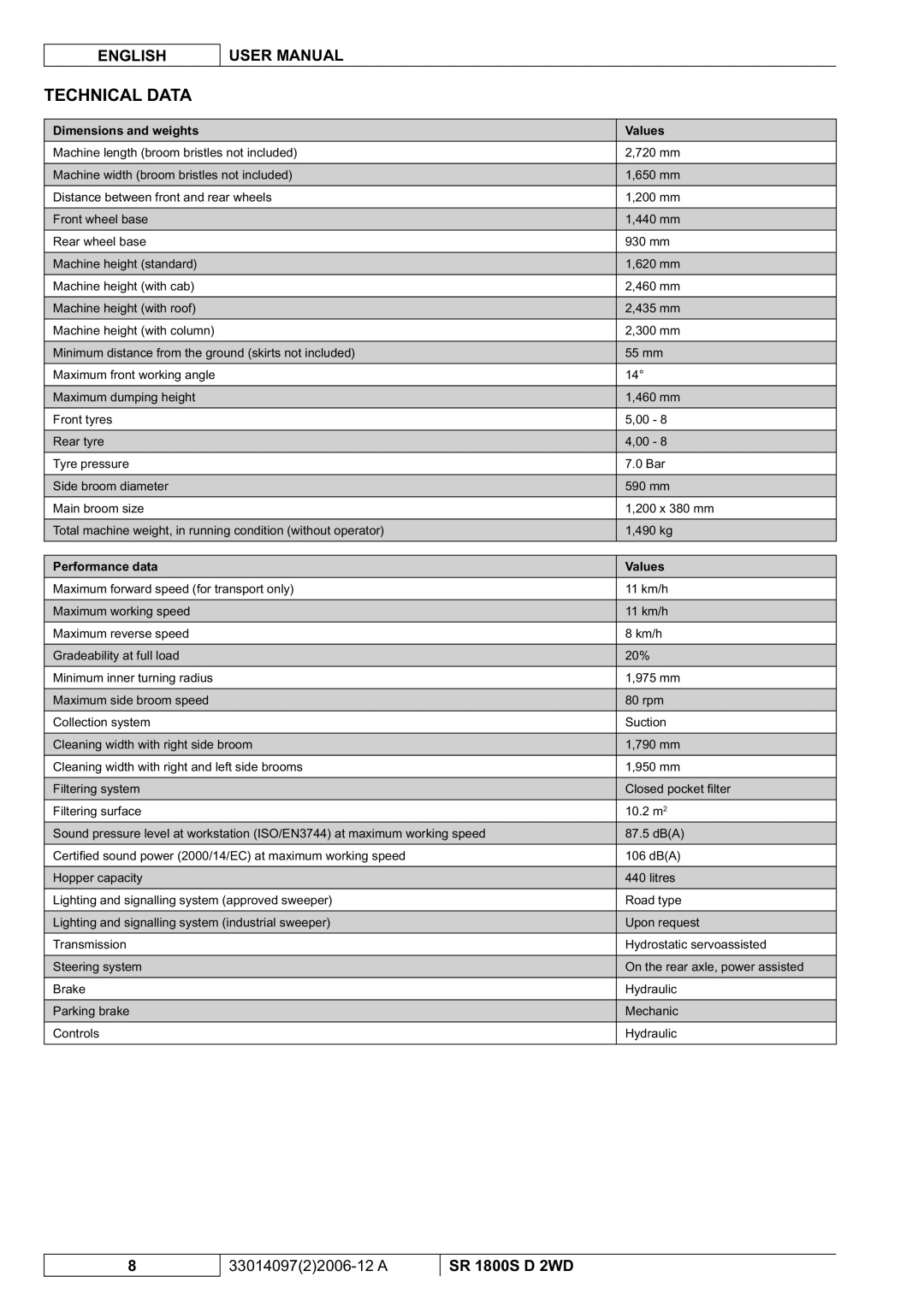
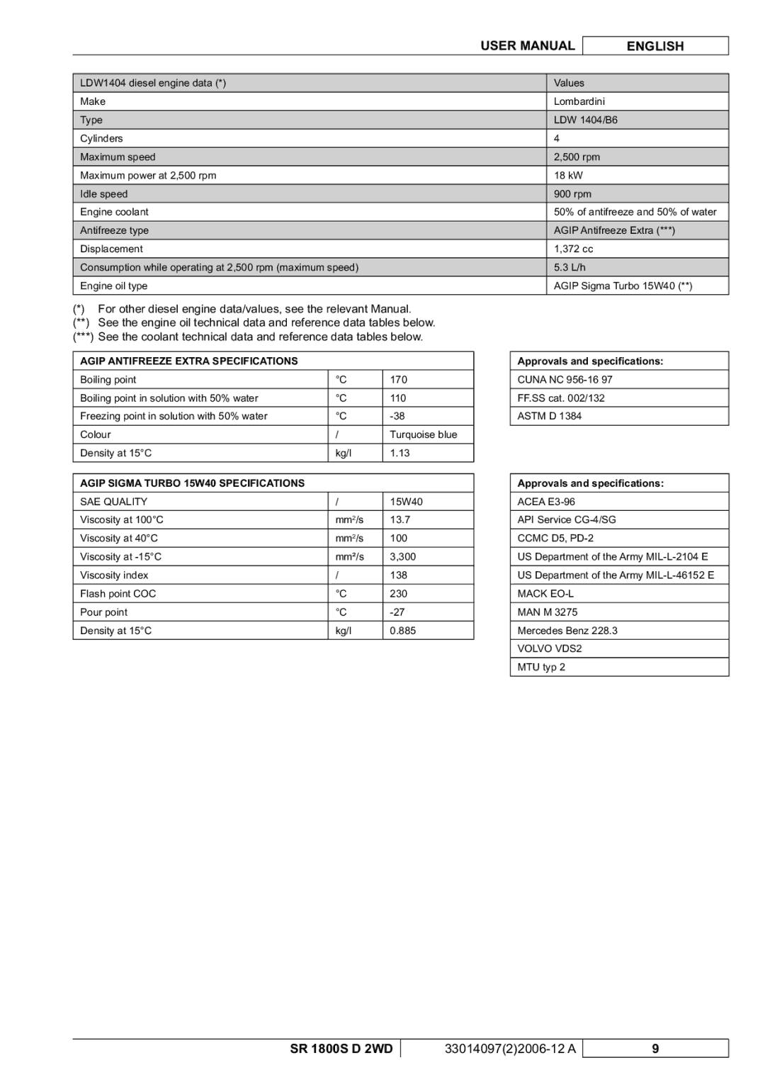
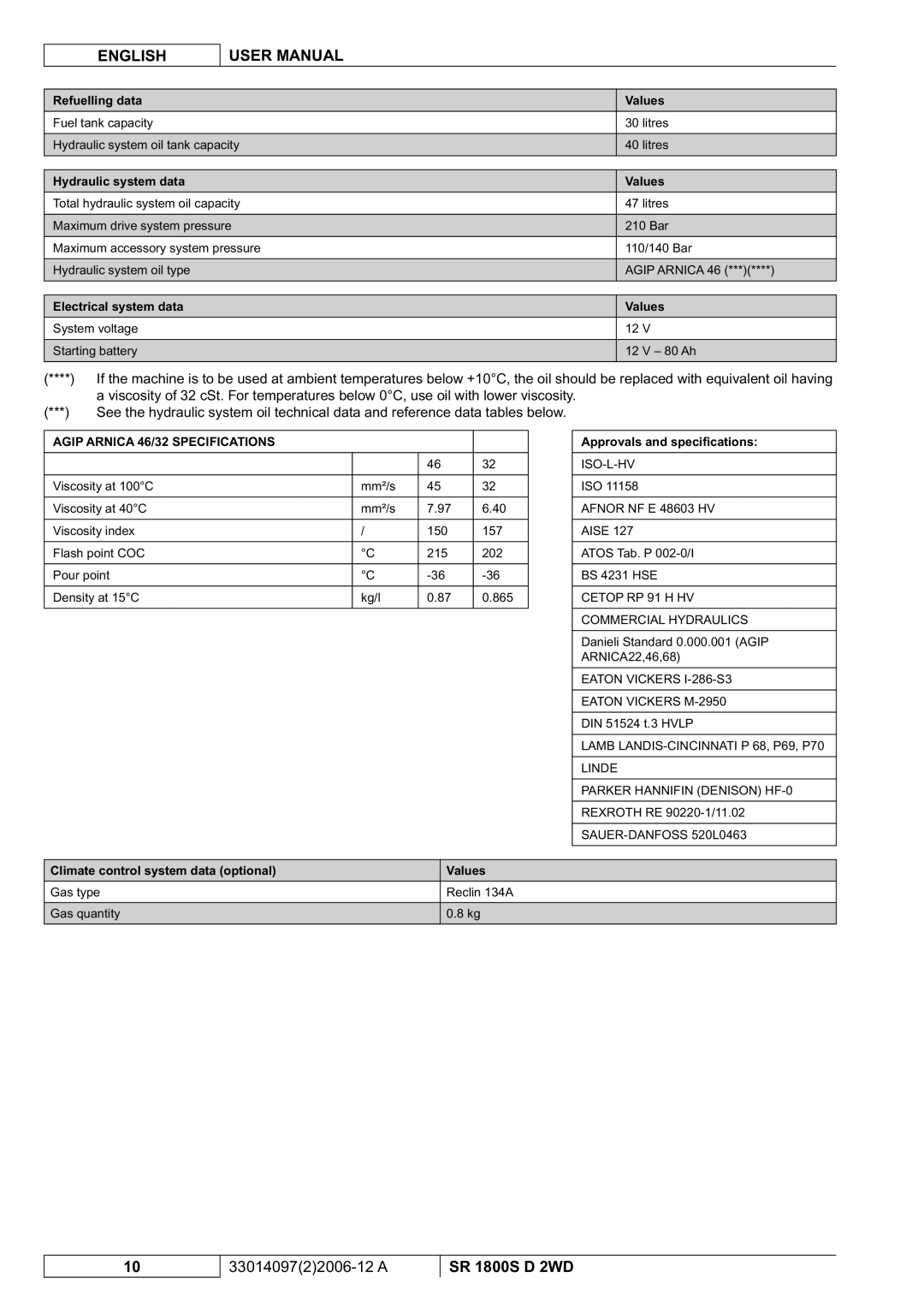
Contents Sweeper Page Inhaltsverzeichnis EinleitungDeutsch Betriebsanleitung Einleitung Sicherheit Verwendete SymboleAllgemeine Hinweise Die befestigten Schildchen nicht entfernen bzw. verändern Funktionseigenschaften AUSPACKEN/LIEFERUNGMaschinenbeschreibung VereinbarungenFunktionen des Kombischalters Beschreibung der Aufstellung der Maschine Siehe Abb. E-FAusmaß- und Gewichtsdaten Werte Technische DatenLeistungsdaten Werte Ccmc D5, PD-2 SAE-KLASSIFIZIERUNGZulassungen und Spezifikationen Mack EO-LDaten elektrische Anlage BetankungsdatenDaten hydraulische Anlage Werte Daten Klimaanlage Option WerteSchaltplan Siehe Abb. AHElektrische Sicherungen HydraulikschaltplanZUBEHÖRE/OPTIONEN Anlassen UND Abstellen Dieselmotor BetriebVOR DEM Anlassen Anlassen DieselmotorMaschinenbenutzung Um den Arbeitszyklus zu beginnen, wie folgt vorgehenGebrauch DER FAHRERKABINEN- Klimaanlage Option Gebrauch DES Linken Seitenbesens OptionGebrauch DES SCHEIBENWISCHERS/- Waschers Option Funktion DER BeleuchtungsanlageSchleppbewegung DER Maschine Einsetzen DER Stützstangen DES AbfallbehältersNach DER Maschinenbenutzung TRANSPORT/BEWEGUNGÜbersichtstabelle DER Planmässigen Wartung WartungWartung Reinigung DES Abfallbehälters Ersetzung DES Ölfilters DER Hydraulikanlage Ersetzung DES StaubtaschenfiltersPrüfung DES Ölstands DER Hydraulikanlage Ölwechsel DER HydraulikanlagePrüfung DES Bremsölstands Funktionsprüfung DES Rückfahralarms OptionPrüfung DES Batterieflüssigkeitsstands Prüfung DES ReifendrucksErsetzung DER Rechten Staubdichtung Prüfung UND Einstellung DER HauptkehrwalzenhöheErsetzung DER Hauptkehrwalze Ersetzung DER Linken StaubdichtungErsetzung DES Dieselmotorölfilters Prüfung DES Ölstands DES DieselmotorsÖlwechsel DES Dieselmotors Ersetzung DES Luftfilters DES DieselmotorsSicherheitsfunktionen Störungen UND Abhilfe FehlersucheStörung Mögliche Ursache Abhilfe Filterrüttler FlapAbfallbehälter LenkungKlimaanlage VerschrottungElektrische Anlage Table DES Matieres IntroductionFrançais Manuel Dutilisation Introduction Securite Symboles UtilisesInstructions Generales Manuel Dutilisation Français Capacites Operationnelles Deballage / LivraisonDescription DE LA Machine ConventionsFonctions du commutateur déclairage Description des composants de la machine Voir Fig. E-FCaracteristiques Techniques Données dimensionnelles et poids ValeursDonnées de performance Valeurs Grade SAE Approbations et spécificationsDonnées système électrique Données ravitaillements ValeursDonnées système hydraulique Valeurs Données système de climatisation optionnel ValeursSchema Electrique Voir Fig. AHAccessoires / Options Schema HydrauliqueProtections Electriques Demarrage ET Arret DU Moteur Diesel UtilisationAvant LA Mise EN Marche Démarrage du moteur dieselUtilisation DE LA Machine Pour commencer un cycle de travail, procéder comme suitFonctionnement DU Systeme Declairage Utilisation DU Balai Lateral Gauche OptionnelUtilisation DE Lessuie Glace / Lave PARE-BRISE Optionnel Actionnement DES Feux DE DetresseApres Lutilisation DE LA Machine Transport / DeplacementInsertion DES Tiges DE Blocage DU Conteneur Dechets Mouvement DE LA Machine PAR RemorquageEntretien Plan Recapitulatif Dentretien ProgrammeNettoyage DU Conteneur Dechets Remplacement DE Lhuile DU Systeme Hydraulique Remplacement DU Filtre a Poussieres a PochesRemplacement DU Filtre DE Lhuile DU Systeme Hydraulique Controle DU Niveau DE Lhuile DU Systeme HydrauliqueControle DU Niveau Dhuile Freins Remplacement DES Balais LaterauxControle DU Niveau DU Liquide DE LA Batterie Controle DE LA Pression DES PneusRemplacement DU Joint Antipoussiere Gauche Remplacement DU Balai CentralRemplacement DU Joint Antipoussiere Droit Remplacement DU Joint Antipoussiere ArriereRemplacement DU Filtre a AIR DU Moteur Diesel Remplacement DE Lhuile DU Moteur DieselRemplacement DU Filtre a Huile DU Moteur Diesel Controle DU Niveau Dhuile DU Moteur DieselRemplacement DES Fusibles Remplacement DU Filtre Carburant DU Moteur DieselRemplacement DU Filtre a AIR Dans LA Cabine DE Conduite Fonctions DE SecuriteDepistage DES Pannes Problemes ET RemedesProblème Cause probable Remède Cause probable Remède Chauffage Dans LA Cabine DE ConduiteClimatiseur Mise EN DechargeSysteme Electrique Table of Contents Hydraulic System OIL Filter Replacement Spare Parts and Maintenance Manual Purpose and ContentsHOW to Keep this Manual Declaration of Conformity TargetSymbols SafetyGeneral Instructions English Operation Capabilities UNPACKING/DELIVERYMachine Description Description of standard control panel See Fig. BCombination switch functions Machine layout description See Fig. E-FDimensions and weights Values Technical DataPerformance data Values SAE Quality Approvals and specificationsElectrical system data Refuelling data ValuesHydraulic system data Values Climate control system data optional ValuesWiring Diagram See Fig. AHACCESSORIES/OPTIONS Hydraulic DiagramElectrical Fuses Diesel Engine Start and Stop USEBefore START-UP Diesel engine startUsing the Machine Remind that the steering is on the rear axleUsing the CAB Climate Control System Optional Using the Left Side Broom OptionalUsing the Windscreen WIPER/WASHER Optional Lighting System OperationTowing the Machine Hopper Support ROD InstallationAfter Using the Machine Transporting by TrailerMaintenance Scheduled Maintenance TableHopper Cleaning 200 600 400Hydraulic System OIL Cooler FIN Cleaning Check Closed Pocket Filter ReplacementHydraulic System OIL Filter Replacement Hydraulic System OIL Level CheckSide Broom Replacement Battery Fluid Level CheckSide Broom Height Check Adjustment Brake Fluid Level CheckRight Dust Panel Replacement Main Broom Height Check and AdjustmentMain Broom Replacement Left Dust Panel ReplacementEngine Radiator FIN Cleaning Check Engine OIL Filter ReplacementEngine AIR Filter Replacement Engine OIL Level CheckSafety Functions Problem Possible cause Remedy TroubleshootingProblems and Remedies BroomsHopper Drive PowerSkirt Filter ShakerClimate Control System ScrappingElectrical System Inhoudsopgave InleidingNederlands Gebruiksaanwijzing Inleiding Veiligheid Gebruikte SymbolenAlgemene Instructies Gebruiksaanwijzing Nederlands Bedrijfscapaciteit Verpakking VERWIJDEREN/ AfleveringBeschrijving VAN DE Machine Algemene OpmerkingenFuncties van de stuurbediening Beschrijving van de instellingen van de machine Zie Afb. E-FAfmetingen en gewichten Waarden Technische EigenschappenPrestaties Waarden Gradatie SAE Goedgekeurde en specifieke vloeistoffenGegevens elektrisch systeem Gegevens oliën WaardenGegevens hydraulisch systeem Waarden Gegevens klimaatregeling optioneel WaardenElektrisch Schema Zie Afb. AHHydraulisch Systeem Accessoires / OptiesElektrische Beschermingen Starten EN Stoppen VAN DE Dieselmotor GebruikVoor HET Starten Starten van de dieselmotorGebruik VAN DE Machine Vergeet niet dat de achteras wordt aangedrevenGebruik VAN DE Klimaatregelaar in DE Stuurcabine Optioneel Gebruik VAN DE Borstel Links OptioneelGebruik VAN Ruitenwissers EN Sproeiers Optioneel Werking VAN HET VerlichtingssysteemVERVOER/BEWEGING NA Gebruik VAN DE MachineTrekbeweging VAN DE Machine Lange Periode VAN StilstandOnderhoud OnderhoudsschemaOnderhoud Inloopperiode naDE Afvalcontainer Reinigen Langere Perio DenDE Oliefilter VAN HET Hydraulisch Systeem Vervangen DE Zakfilter VervangenControle VAN HET Oliepeil VAN HET Hydraulische Systeem DE Olie VAN HET Hydraulisch Systeem VerversenControle VAN DE Bandenspanning Controle VAN HET Vloeistofpeil VAN DE AccuControle VAN HET Remoliepeil DE Hoogte VAN DE Zijborstels Controleren EN AfstellenDE Stofafdichting Links Vervangen DE HoofdborstelvervangenDE Stofafdichting Rechts Vervangen DE Stofafdichting Achter VervangenVervanging VAN DE Oliefilter VAN DE Dieselmotor Controle VAN HET Oliepeil VAN DE DieselmotorVerversing VAN DE Olie VAN DE Dieselmotor DE Luchtfilter VAN DE Dieselmotor VervangenDE Luchtfilter VAN DE Stuurcabine Vervangen VeiligheidsfunctiesDE Brandstofluchtfilter VAN DE Dieselmotor Vervangen Vervanging VAN DE ZekeringenOngemakken EN Herstelacties Storingen LokaliserenOngemak Waarschijnlijke oorzaak Herstelactie Stuurinrichting AfvalcontainerFilterschudder RemmenKlimaatregelaar VerwijderingElektrisch Systeem Directive 98/37/EC Directive 73/23/EE00000,00h III 40 40 SR 1800S D 2WD 3301409722006-12 a ÷3,9inc 40÷100mmVII Viii F13 F14 F18 F16 12 a