Part No -1742-001 Published May
3Com Corporation 5400 Bayfront Plaza Santa Clara, California
Contents
Installing and Connecting the NIC
Installing Dynamicaccess Software in Windows
Installing Netware Client and Server Drivers
Configuring the NIC
Troubleshooting the NIC
Ethercd Content and Navigation
Technical Support
NIC/Description Model Number
About this Guide
Convention Description
Conventions
Icon Description
Product Name/Description Model Number
Overview
LAN Encryption Software for Windows 95/98
Onboard 3XP Processor
Data Encryption
High Encryption Pack for Windows
3CR990 NIC Features
3XP Processor
Advanced Server Features
Failover
Load Balancing
Self-Healing Drivers
Primary failure
VLANs
Traffic Prioritization
Remote Wake-Up
Server Features Using Other NICs
Windows NT and Windows 2000-Planning the Configuration on
Remote Wake-Up Requirements
Remote Wake-Up Cable
Integrated Boot ROM with Managed PC Boot Agent MBA
Remote Wake-Up and Multiple NIC Installations
Desktop Management Interface DMI
Dhcp Server Prevention
Hot Plug NIC Installation
Remote System Alerts
Offline Diagnostics
DynamicAccess LAN Agent
Windows 2000 Offload Features
Safety Precautions
Installation Overview
RAM
Installation Requirements
Installing Multiple NICs
Installing From Diskette
Upgrading Windows 95 to Windows
Updating the Network Driver and NIC Software
Creating Installation Diskettes
Making a DOS-Bootable Diskette
Product Registration
Decide whether you want to use Remote Wake-Up
Preparing the NIC and the Computer
Follow the prompts as they appear
Network Envi Cable Required Maximum Ronment Cable Length
Make sure that cable requirements are met
Installing and Connecting the NIC
Carefully insert the NIC in the empty PCI slot, as shown
Replace the computer cover and plug in the power cord
Connecting the cable to the NIC backplate
Connecting the Remote Wake-Up Cable
Replace the PC cover and plug in the power cord
Installing Software
Software Installation Requirements
Installing NIC Drivers Windows
Windows
Installing the Network Driver Using the EtherCD
Getting Help
Click Finish
Windows NT
Click Next
Click Close
Click Add
Click Yes to restart the PC
Turn the PC power on
Click Yes to restart your computer
You must restart your computer to complete the installation
New Hardware Found
Click Yes
Update Device Driver Wizard
Do one of the following
Enter the path to the CD-ROM drive, and then click OK
Right-click the My Computer icon, and then click Properties
Verifying Successful Installation
Select the Resources tab
Windows 95 and Windows
Installing the 3Com NIC Diagnostics Program
Double-click the 3Com NIC Diagnostics icon
Starting the 3Com NIC Diagnostics Program
Updating the Network Driver and NIC Software
Restart Windows
Windows 2000, Windows 98, and Windows
Installing Multiple NICs
Insert the EtherCD
Repeat the process for each additional NIC to be installed
Select the Adapters tab Click Add
Close the Network screen
Client PC Requirements
Installing the DynamicAccess LAN Agent for a Client NIC
Installing the LAN Agent
Restart the PC
Verifying Successful Installation
Configuring the DynamicAccess LAN Agent
Start Windows Insert the EtherCD in the CD-ROM drive
Installing DynamicAccess Software for a Server NIC
Removing the DynamicAccess LAN Agent
Installing DynamicAccess Software for a Server NIC
Planning the Configuration
Configuring Groups and VLANs for a Server NIC
Configuring Groups and VLANs for a Server NIC
Number of VLANs
Windows
Working With Server Features
Windows NT
Creating a Group
Double-click the DynamicAccess SW Server icon
To disable all load balancing-Clear
Specifying a Dedicated IP Address
Adding NICs to a Group
Click the Load Balance/RSL tab Load Balance/RSL window
Click Add NIC
Creating a Vlan
Changing an IP Address
Click the appropriate tab
Specifying Traffic Priorities
Saving the Configuration
Changing the Primary NIC
Disabling Load Balancing for a Group
Removing a NIC from a Group
Click the Load Balance/RSL tab
Displaying NIC Properties
Deleting or Editing a Vlan
Displaying Group Properties
Specifying Failover from Gigabit to 10/100 PCI
Disable load balancing for the group
Troubleshooting a Load Balancing Configuration
Symptom Tip
Add 3Com server NICs to the group
Identifying Windows 2000 Miniport and LAN Connections
Changing Windows 2000 Property Settings
Using Windows 2000 Offload Features
Enabling Offloads
Click Configure
Value Offload Function Enabled
Configuring Offloads for a Group of Different NICs
Installing DynamicAccess LAN Encryption Software
Installing LAN Encryption Software on Windows
Minimum Installation Requirements
Hardware Requirements
Software Requirements
Click NIC Software
Click Yes to continue
Click Yes Click OK
With the Winsock2 Setup screen displayed, click OK Click OK
Enter your network password when prompted
Insert the Windows 95 CD-ROM and click OK
Installing LAN Encryption Software on Windows
Click Yes to continue
Installing Dynamicaccess Software in Windows
Adding the Entrust File
Viewing the Administrator’s Guide Online
Starting DynamicAccess LAN Encryption Software
Uninstalling LAN Encryption Software
Page
NetWare Version Required Support Pack Latest patch files
Installing and Configuring the NetWare Server Driver
Using the Latest Support Packs
NetWare Server NLM Name
Obtaining NetWare Loadable Modules
NetWare Version Required Support Pack
Before installing NICs After installing two NICs
Server Software Installation Requirements
Netware Packet Receive Buffers
Slot Numbers for Multiple NICs
Obtaining Slot Numbers
Installing the NetWare 3.12 Server Driver
Save and exit the file, and then reboot the server
Press Insert again
Press Enter
Select 3C99x, and then press Enter
Type the name of the NIC and press Enter
Select Reinitialize System
Press Enter to save the changes
Press Esc to Exit
Press Enter to select the driver
Loading the 3Com EtherCD
Loading the Driver
Specifying the Slot Number
Load 3C99X.LAN slot=slot1 NAME=name1 FRAME=frametype1
Installing Multiple Server NICs
Boot the NetWare server with the -na option
Installing Server Features
Verifying the PCI Slot Number
From the Configuration Options screen select Product options
Make the following changes to the AUTOEXEC.NCF file
Enter this command
Configuring Groups
Save the AUTOEXEC.NCF file and return to the server prompt
Select a driver to view its associated statistics
Verifying the Installation and Configuration
At the system prompt, enter load monitor
Parameter Range of Values Description
Changing NetWare Driver Configuration Parameters
Log in or map to the server
Maintaining Groups
Adding a Secondary NIC to a Group
Install the new secondary NIC
Reboot the server
Adding a Group
Install the NICs
107
Display status
Server Feature Commands
Group
Probe interval
Link timeout
Help
Retry count
Receive timeout
Send timeout
Ungroup
Wait timeout
Troubleshooting a Group Configuration
Option Description Settings
Default NIC Settings
Auto Select
ALL
Method Description Requirements
Configuration Methods
Method Description
Changing General NIC Configuration Settings
Using the 3Com NIC Diagnostics Program
Click OK to save the changes and exit the program
Using the 3Com DOS Configuration Program
Enter the following at the DOS prompt d\3c99xcfg.exe
Booting From the Network
Configuring the Managed PC Boot Agent MBA
Enabling or Disabling the Boot ROM Setting
Make sure that the NIC boot ROM setting is Enabled
BBS BIOS-Compatible PCs
Set the MBA manually as the first boot device
Reboot the PC
Disabling the 3Com Logo
Non-BBS BIOS-Compatible PCs
Change the MBA default boot setting from Local to Network
Encryption Description Type Level
Configuring IP Security
Defining the Console
Creating a Security Policy
Click Next and then Finish
Creating the Policy
Select IP Security Policy Management, and then click Add
Enter destination IP address, and then click Next
Creating a Filter
Select a Specific IP Address in the pull-down list
Binding the Filter
Accept the default, and then click Next
Creating the Filter Action
Binding the Filter Action
Disabling Encryption
Enabling Encryption
State Meaning
Interpreting the LEDs
LNK
Viewing the NIC LEDs in the Diagnostics Program
Accessing the 3Com Knowledgebase
Accessing 3Com Support Databases
Accessing the 3Com NIC Help System
Accessing Release Notes and Frequently Asked Questions
Cleaning Up a Failed Installation
Troubleshooting the NIC Installation
Problems/Error Messages
Click Proceed Click OK
Troubleshooting the Network Connection
Tip Description
Make sure that you are using the latest driver for the NIC
Troubleshooting Remote Wake-Up
Check the computer Bios
Check the Remote Wake-Up cable connection
Connect a straight-through cable from the PC to the hub
Troubleshooting a Network Connection
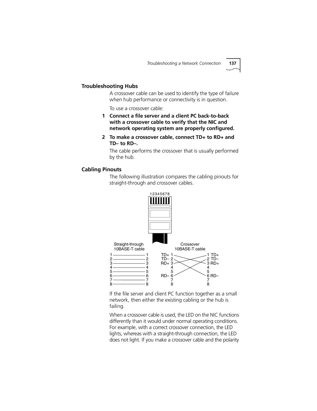
Cabling Pinouts
Troubleshooting Hubs
Exit the Device Manager and shut down Windows
Removing the Network Driver
Click the Device Manager tab
From the Start menu, select Settings/Control Panel
Removing DynamicAccess Server Features
NetWare
Enter this command at the prompt
Page
Running NIC Diagnostics
Reboot the computer using a DOS-bootablediskette
Running the 3Com DOS Diagnostics Program
Running the NIC Diagnostics Tests
Tab Description
Running the Network Test
Running the NIC Test
Viewing the NIC LEDs in the Diagnostics Program
Click the Statistics tab. The Statistics screen appears
Viewing Network Statistics
Displaying Network Statistics
Using the 3Com Icon in the Windows System Tray
Enabling the Icon
Click Proceed, and then follow the prompts on the screen
Removing the 3Com NIC Diagnostics Program
Page
Obtaining Drivers
Page
3CR990 NIC Specifications
Specifications
Twisted-Pair Cable
Cabling Requirements
Category Use
10BASE-T Operation
100BASE-TX Operation
RJ-45 Connector Pin Assignments
Link Negotiation
Flow Control
Pause Frames
Page
About the 3Com DMI Agent
3C OM DMI a Gent
System Requirements
Follow the prompts on the screen
Installing the 3Com DMI Agent
Network Management Requirements
Restart the PC when prompted
LinksDescription
EtherCD Navigation
Auto Insert
Root Subdirectories
Text Files
Subdirectory Description
File Name File Description
165
Page
Requirements
Windows Fresh Installation
NetWare Fresh Installation
Driver Summary screen, select 3C990.LAN and press Enter
Installation Instructions
When the installation is finished, edit the STARTUP.NCF file
Page
World Wide Web Site
Online Technical Services
3Com Bulletin Board Service
3Com Knowledgebase Web Services
Access by Analog Modem
3Com FTP Site
Access by Digital Modem
3Com Facts Automated Fax Service
Support from Your Network Supplier
847 262
Europe
Support from 3Com
Country Region Telephone Number Asia Pacific Rim
Country Region
Returning Products for Repair
Europe, South Africa, and Middle East
Latin America
Country Region Telephone Number Fax Number
To obtain an authorization number, call or fax
Numbers
Index
MBA
PCI NIC
131
NLMs
Displaying, Windows
Self-healing drivers SHDs
OSR2
Index
Page
FCC Class B Statement
Industry Canada Class B Emission Compliance Statement
Page
Product Registration