Step 3 The display on the monitor will show
Communication Errors”. Otherwise go to step 4.
Note: If possible, keep the cable connected to the computer unless the port is needed for other functions.
Step 4 Run the software.
Step 5 Confirm that the correct serial port and the correct monitor type are set. For details, see
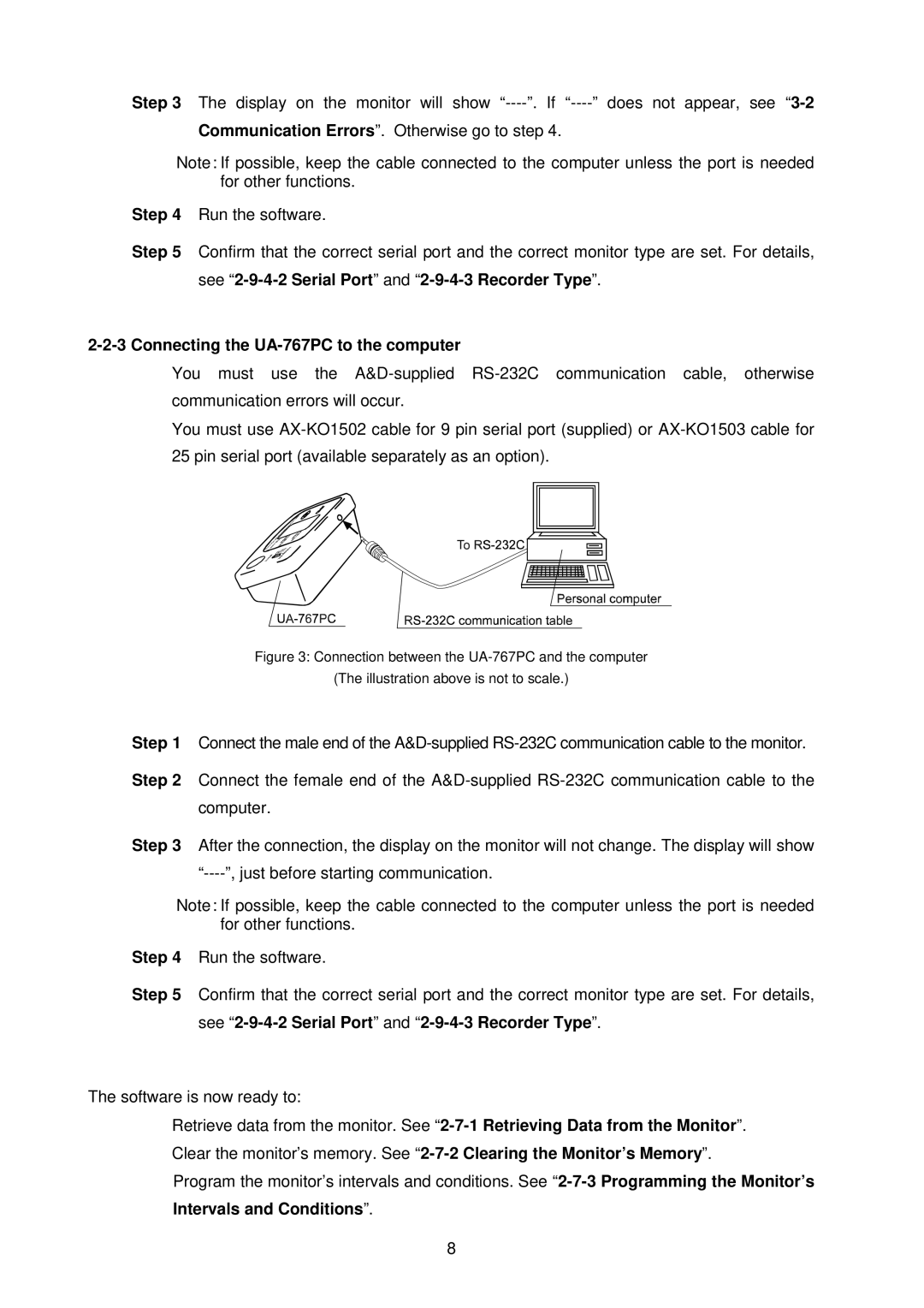
2-2-3 Connecting the UA-767PC to the computer
♦You must use the
♦You must use
Figure 3: Connection between the UA-767PC and the computer
(The illustration above is not to scale.)
Step 1 Connect the male end of the
Step 2 Connect the female end of the
Step 3 After the connection, the display on the monitor will not change. The display will show
Note: If possible, keep the cable connected to the computer unless the port is needed for other functions.
Step 4 Run the software.
Step 5 Confirm that the correct serial port and the correct monitor type are set. For details, see
The software is now ready to:
♦Retrieve data from the monitor. See
♦Clear the monitor’s memory. See
♦Program the monitor’s intervals and conditions. See
8