2.3.3 Two/Three/Four-Wire RTD
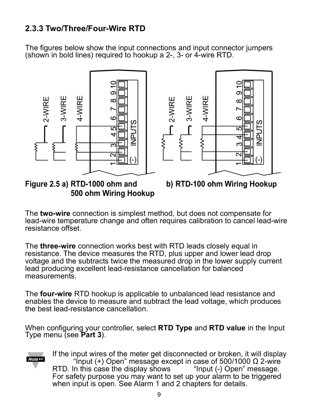
The figures below show the input connections and input connector jumpers (shown in bold lines) required to hookup a 2-, 3- or 4-wire RTD.
Figure 2.5 a) RTD-1000 ohm and | b) RTD-100 ohm Wiring Hookup |
500 ohm Wiring Hookup | |
The two-wireconnection is simplest method, but does not compensate for lead-wire temperature change and often requires calibration to cancel lead-wire resistance offset.
The three-wireconnection works best with RTD leads closely equal in resistance. The device measures the RTD, plus upper and lower lead drop voltage and the subtracts twice the measured drop in the lower supply current lead producing excellent lead-resistance cancellation for balanced measurements.
The four-wireRTD hookup is applicable to unbalanced lead resistance and enables the device to measure and subtract the lead voltage, which produces the best lead-resistance cancellation.
When configuring your controller, select RTD Type and RTD value in the Input Type menu (see Part 3).
If the input wires of the meter get disconnected or broken, it will display +OPN “Input (+) Open” message except in case of 500/1000 Ω 2-wire RTD. In this case the display shows -OPN “Input (-) Open” message. For safety purpose you may want to set up your alarm to be triggered when input is open. See Alarm 1 and 2 chapters for details.