C
Dimension Drawings
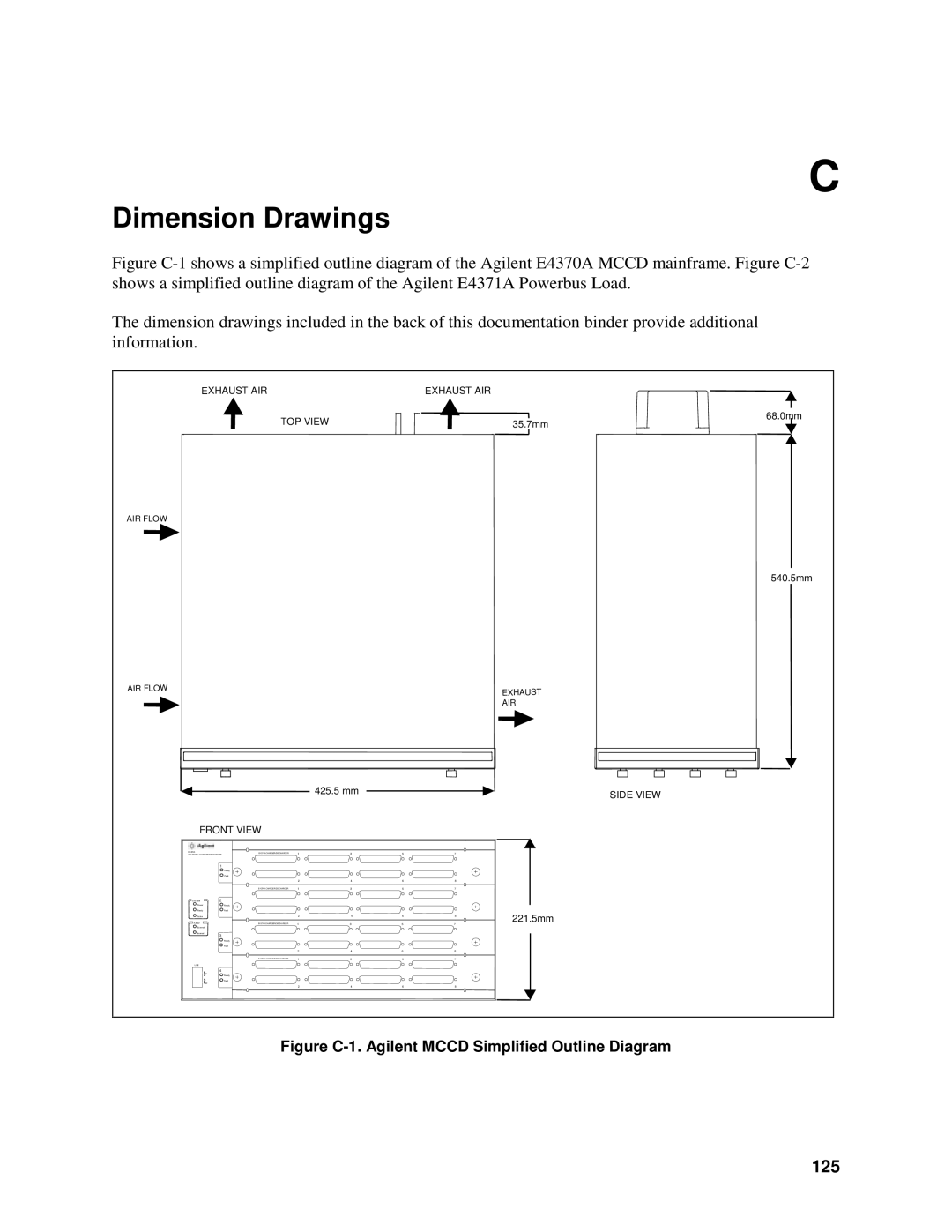
Figure C-1 shows a simplified outline diagram of the Agilent E4370A MCCD mainframe. Figure C-2 shows a simplified outline diagram of the Agilent E4371A Powerbus Load.
The dimension drawings included in the back of this documentation binder provide additional information.
EXHAUST AIR
TOP VIEW
EXHAUST AIR
68.0mm
35.7mm
AIR FLOW
540.5mm
AIR FLOW | EXHAUST |
| |
| AIR |
|
|
|
| 425.5 mm |
|
| SIDE VIEW |
|
|
|
|
|
|
| |
FRONT VIEW |
|
|
|
|
| ||
E4370A |
| E4374A CHARGER/DISCHARGER | 1 | 3 | 5 | 7 |
|
MULTICELL CHARGER/DISCHARGER |
| ||||||
| 1 |
|
|
|
|
|
|
|
| Ready |
|
|
|
|
|
|
| Fault |
|
|
|
|
|
|
|
| 2 | 4 | 6 | 8 |
|
|
| E4374A CHARGER/DISCHARGER | 1 | 3 | 5 | 7 |
|
SYSTEM | 2 |
|
|
|
|
|
|
Power |
| Ready |
|
|
|
|
|
Ready |
| Fault |
|
|
|
| 221.5mm |
Active |
|
| 2 | 4 | 6 | 8 | |
FAULT |
| E4374A CHARGER/DISCHARGER | 1 | 3 | 5 | 7 |
|
External |
|
|
|
|
|
|
|
Internal | 3 |
|
|
|
|
|
|
|
|
|
|
|
|
| |
|
| Ready |
|
|
|
|
|
|
| Fault |
|
|
|
|
|
|
|
| 2 | 4 | 6 | 8 |
|
|
| E4374A CHARGER/DISCHARGER | 1 | 3 | 5 | 7 |
|
LINE |
|
|
|
|
|
|
|
| 4 |
|
|
|
|
|
|
| On | Ready |
|
|
|
|
|
|
|
|
|
|
|
| |
|
| Fault |
|
|
|
|
|
| Off |
|
|
|
|
|
|
|
|
| 2 | 4 | 6 | 8 |
|