3 - Configuration
In the COM
Properties box:
select the following port settings:
Bits per second | 9600 |
Data bits | 8 |
Parity | None |
Stop Bits | 1 |
Flow control | None |
Then click OK.
In the File menu
In the Properties box:
Select the Properties command
Select the Settings tab. Under Emulation, make sure that Auto detect is selected. Click the ASCII Setup button and make the following selections:
Send line ends with line feeds | Not checked |
Echo Typed Characters locally | Checked |
Line delay | 0 |
Character delay | 0 |
Append line feeds to incoming cone ends | Not checked |
Force incoming data to | Not checked |
Wrap lines that exceed terminal width | Not checked |
Click OK to exit ASCII Setup. |
|
|
|
Click OK to exit Properties |
|
|
|
2. Connect the Agilent E4370A MCCD to the COM port on the PC
Connect the ac line cord to the LINE connector on the rear of the unit Agilent MCCD. This is a universal ac input that supports any line voltage from 87 Vac to 250 Vac, 50/60 Hz.
Turn on the Agilent MCCD.
If you have not already done so, connect the Agilent E4370A MCCD to the COM port on the PC. Connect the
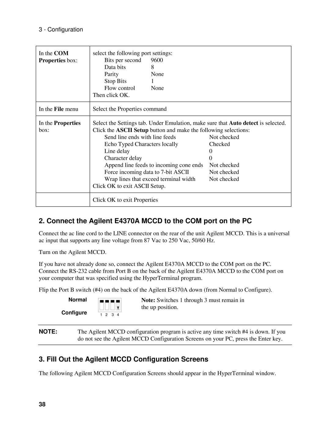
Flip the Port B switch (#4) on the back of the Agilent E4370A down (from Normal to Configure).
Normal
Configure | 1 | 2 | 3 | 4 |
|
Note: Switches 1 through 3 must remain in the up position.
NOTE: The Agilent MCCD configuration program is active any time switch #4 is down. If you do not see the Agilent MCCD Configuration Screens on your PC, press the Enter key.
3. Fill Out the Agilent MCCD Configuration Screens
The following Agilent MCCD Configuration Screens should appear in the HyperTerminal window.
38