2 - Installation
Isolated Output When outputs are configured for optically isolated mode, they are
Special Functions
External Fault Input
When true, this signal stops the cell forming sequence due to an external fault condition. It also sets the external fault output signal true. This signal can be connected to a sensor such as a fire detector. It can also be connected to the external fault output of another Agilent MCCD so that it can respond to a fault in another mainframe.
External Fault Output
This signal is asserted true when an external fault occurs. It can be connected to external equipment such as a fire alarm. It can also be connected to the external fault input of another mainframe so that a fault in one mainframe can shut down other mainframes. A cfProtectClear command clears this signal.
External Interlock | When true, this signal stops the cell forming sequence, but because the stop was not |
| due to a fault condition, it does not set the external fault output signal true. This |
| |
| an operator or mechanical device to stop a cell forming sequence. When the signal |
| is removed, the sequence continues. |
External Trigger | This external trigger input is used to start the cell forming sequence. |
Power Fail | Depending on how the system is configured, when true, this input signal will cause |
| the Agilent MCCD to perform a shutdown, at which time it saves its state for a later |
| restart. A power fail output signal is also available to indicate when the shutdown |
| state has been saved. |
Wiring Guidelines
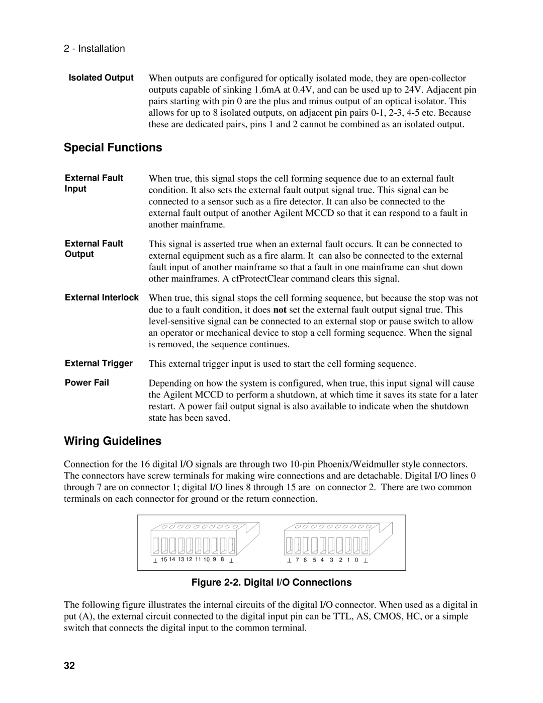
Connection for the 16 digital I/O signals are through two
⊥ 15 14 13 12 11 10 9 8 ⊥ | ⊥ 7 6 5 4 3 2 1 0 ⊥ |
|
|
Figure 2-2. Digital I/O Connections
The following figure illustrates the internal circuits of the digital I/O connector. When used as a digital in put (A), the external circuit connected to the digital input pin can be TTL, AS, CMOS, HC, or a simple switch that connects the digital input to the common terminal.
32