1
General Information
Agilent MCCD System Capabilities
The Agilent
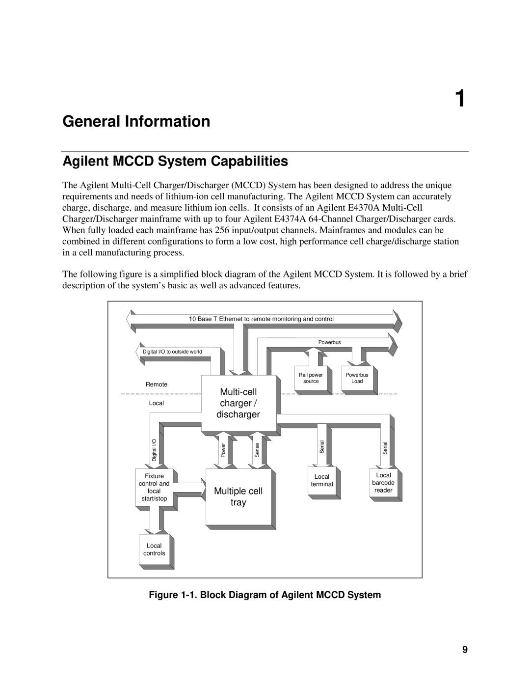
The following figure is a simplified block diagram of the Agilent MCCD System. It is followed by a brief description of the system’s basic as well as advanced features.
10 Base T Ethernet to remote monitoring and control
Digital I/O to outside world |
|
Remote | |
| |
Local | charger / |
| discharger |
Digital I/O | Power | Sense |
Fixture |
|
control and | Multiple cell |
local | |
start/stop | tray |
|
Powerbus |
|
Rail power | Powerbus |
source | Load |
Serial | Serial |
Local | Local |
terminal | barcode |
| reader |
Local
controls
Figure 1-1. Block Diagram of Agilent MCCD System
9