D
Sense and Power Connector Pinouts
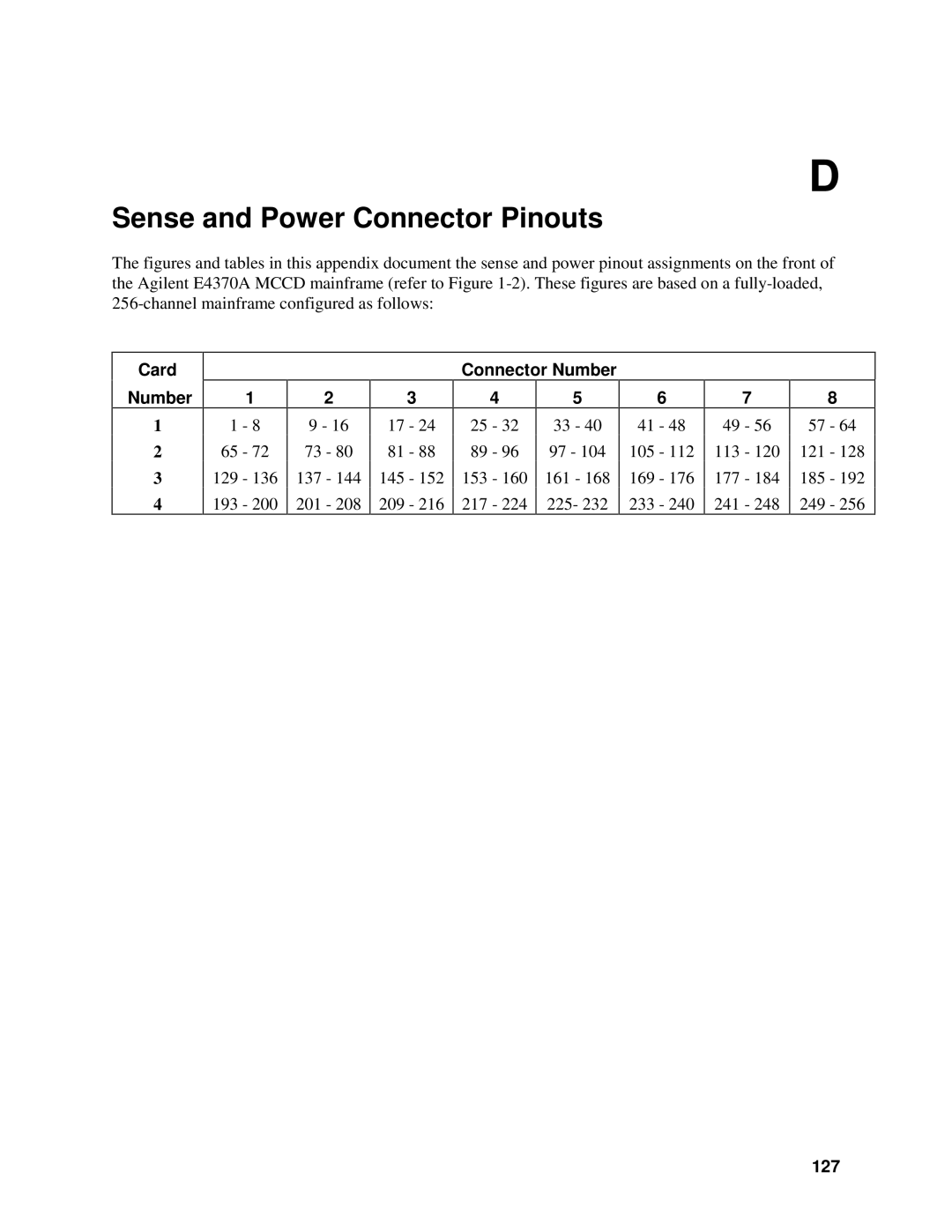
The figures and tables in this appendix document the sense and power pinout assignments on the front of the Agilent E4370A MCCD mainframe (refer to Figure 1-2). These figures are based on a fully-loaded,
256-channel mainframe configured as follows:
Card
Number
1
2
3
4
| 1 |
| 2 |
| 3 |
1 | - 8 | 9 - 16 | 17 | - 24 | |
65 | - 72 | 73 | - 80 | 81 | - 88 |
129 | - 136 | 137 | - 144 | 145 | - 152 |
193 | - 200 | 201 | - 208 | 209 | - 216 |
Connector Number
| 4 |
|
| 5 |
25 | - | 32 | 33 | - 40 |
89 | - | 96 | 97 - 104 | |
153 | - | 160 | 161 | - 168 |
217 | - | 224 | 225- 232 | |
6
41 - 48
105 - 112
169 - 176
233 - 240
7
49 - 56
113 - 120
177 - 184
241 - 248
8
57 - 64
121 - 128
185 - 192
249 - 256