1 2 3 4 5
6 7 8 9
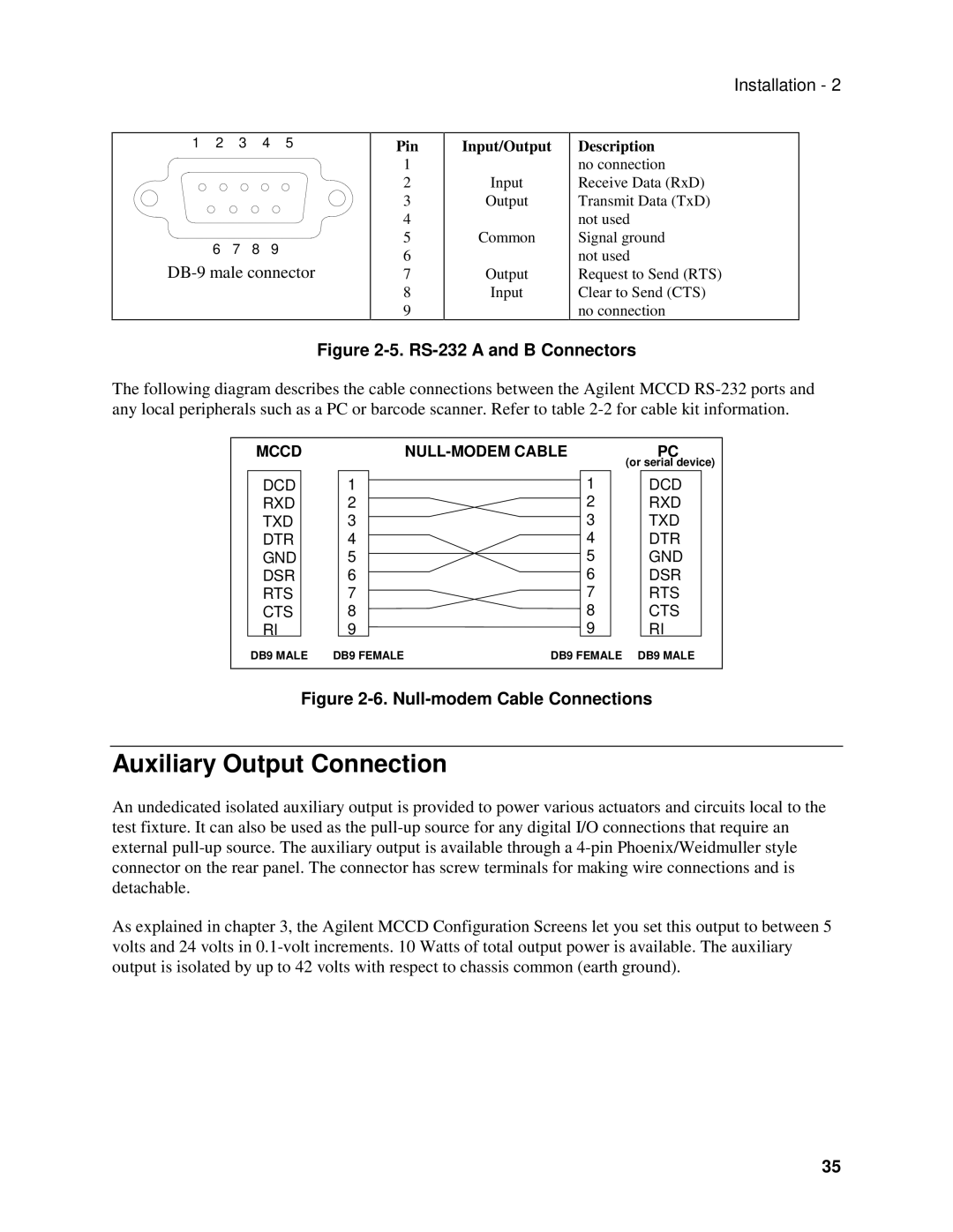
Pin
1
2
3
4
5
6
7
8
9
Input/Output
Input
Output
Common
Output
Input
Installation - 2
Description no connection Receive Data (RxD) Transmit Data (TxD) not used
Signal ground not used
Request to Send (RTS) Clear to Send (CTS) no connection
Figure 2-5. RS-232 A and B Connectors
The following diagram describes the cable connections between the Agilent MCCD
MCCD |
| PC | |
|
|
| (or serial device) |
DCD | 1 | 1 | DCD |
RXD | 2 | 2 | RXD |
TXD | 3 | 3 | TXD |
DTR | 4 | 4 | DTR |
GND | 5 | 5 | GND |
DSR | 6 | 6 | DSR |
RTS | 7 | 7 | RTS |
CTS | 8 | 8 | CTS |
RI | 9 | 9 | RI |
DB9 MALE | DB9 FEMALE | DB9 FEMALE | DB9 MALE |
|
|
|
|
Figure 2-6. Null-modem Cable Connections
Auxiliary Output Connection
An undedicated isolated auxiliary output is provided to power various actuators and circuits local to the test fixture. It can also be used as the
As explained in chapter 3, the Agilent MCCD Configuration Screens let you set this output to between 5 volts and 24 volts in
35