IX5-28GPX Installation Guide
RJ-45 Twisted Pair Port Pinouts
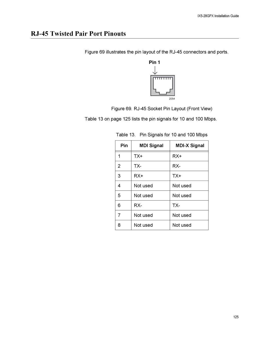
Figure 69 illustrates the pin layout of the RJ-45 connectors and ports.
Figure 69. RJ-45 Socket Pin Layout (Front View)
Table 13 on page 125 lists the pin signals for 10 and 100 Mbps.
Table 13. Pin Signals for 10 and 100 Mbps
Pin | MDI Signal |
|
|
|
|
|
|
|
1 | TX+ | RX+ |
|
|
|
2 | TX- | RX- |
|
|
|
3 | RX+ | TX+ |
|
|
|
4 | Not used | Not used |
|
|
|
5 | Not used | Not used |
|
|
|
6 | RX- | TX- |
|
|
|
7 | Not used | Not used |
|
|
|
8 | Not used | Not used |
|
|
|
125