Chapter 1: Overview
LEDs for the
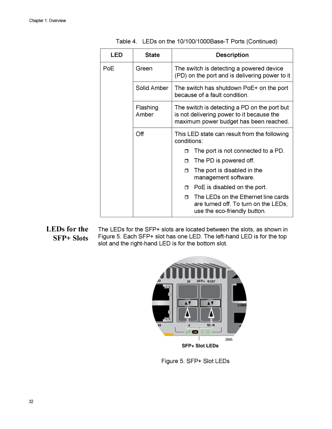
SFP+ Slots
Table 4. LEDs on the
LED | State | Description |
|
|
|
PoE | Green | The switch is detecting a powered device |
|
| (PD) on the port and is delivering power to it |
|
|
|
| Solid Amber | The switch has shutdown PoE+ on the port |
|
| because of a fault condition. |
|
|
|
| Flashing | The switch is detecting a PD on the port but |
| Amber | is not delivering power to it because the |
|
| maximum power budget has been reached. |
|
|
|
| Off | This LED state can result from the following |
|
| conditions: |
|
| The port is not connected to a PD. |
|
| The PD is powered off. |
|
| The port is disabled in the |
|
| management software. |
|
| PoE is disabled on the port. |
|
| The LEDs on the Ethernet line cards |
|
| are turned off. To turn on the LEDs, |
|
| use the |
|
|
|
The LEDs for the SFP+ slots are located between the slots, as shown in Figure 5. Each SFP+ slot has one LED. The
SFP+ Slot LEDs
Figure 5. SFP+ Slot LEDs
32