x510 Series Installation Guide for Virtual Chassis Stacking
Unpacking the Switch
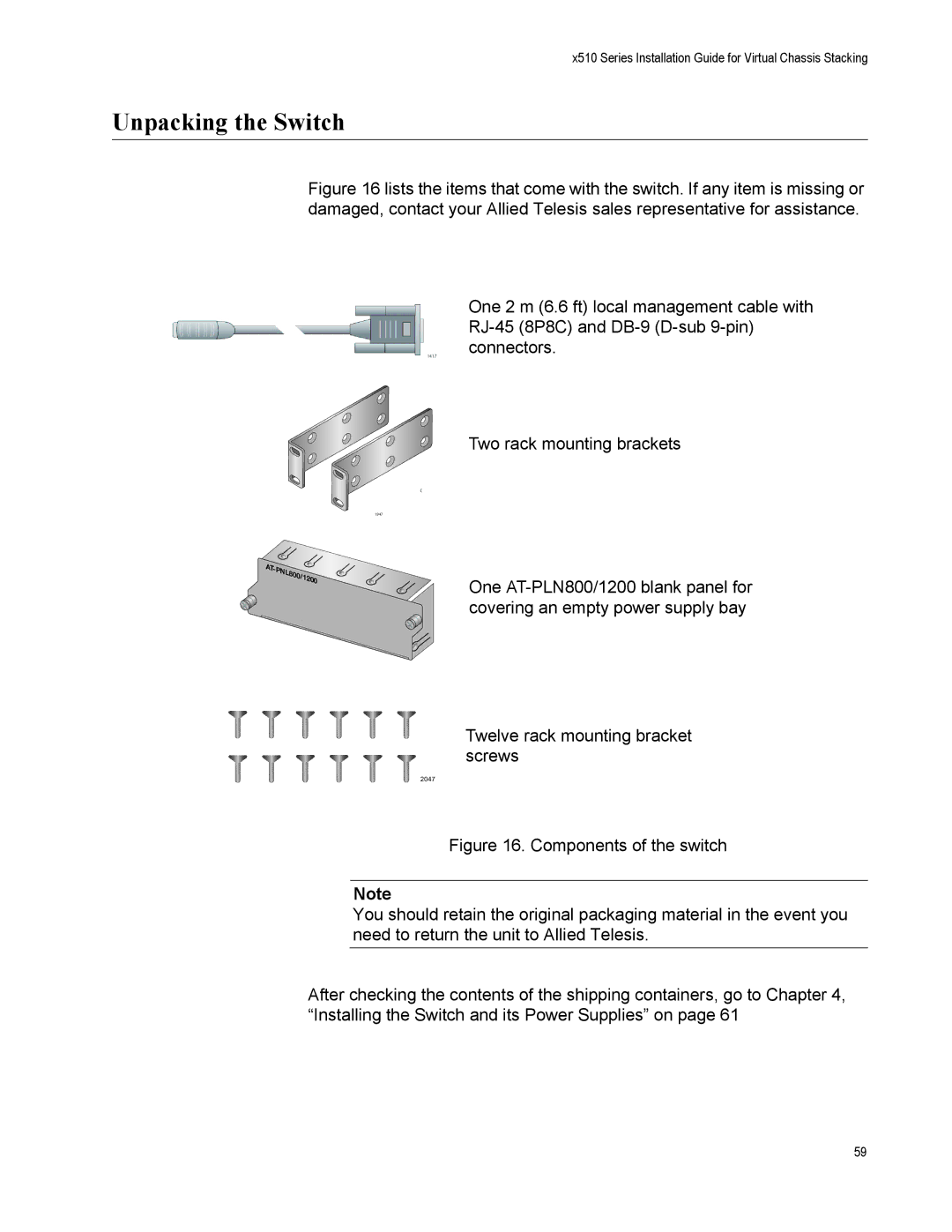
Figure 16 lists the items that come with the switch. If any item is missing or damaged, contact your Allied Telesis sales representative for assistance.
One 2 m (6.6 ft) local management cable with
Two rack mounting brackets
1947
One
Twelve rack mounting bracket screws
2047
Figure 16. Components of the switch
Note
You should retain the original packaging material in the event you need to return the unit to Allied Telesis.
After checking the contents of the shipping containers, go to Chapter 4, “Installing the Switch and its Power Supplies” on page 61
59