IX5-28GPX Installation Guide
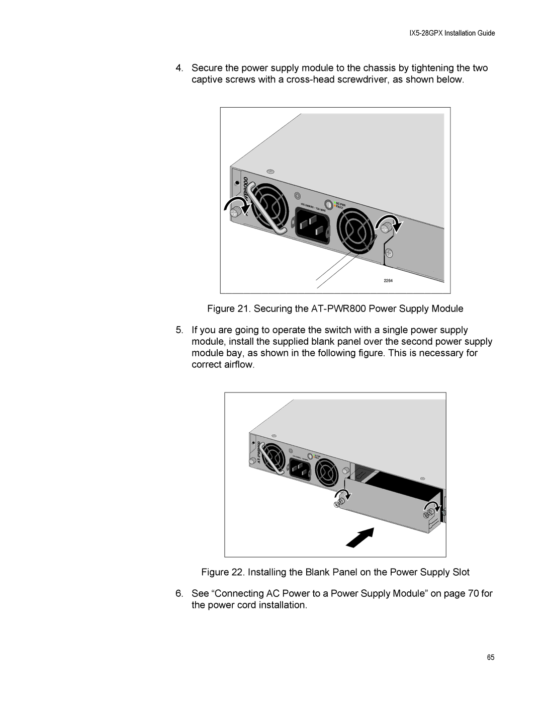
4.Secure the power supply module to the chassis by tightening the two captive screws with a
PWR8000 | 100 |
|
| DC | PWR | |
|
|
| FA | |||
|
| VAC~ | 12A | MAX | ULT | |
|
|
|
|
|
| |
|
|
|
|
|
| 2264 |
Figure 21. Securing the AT-PWR800 Power Supply Module
5.If you are going to operate the switch with a single power supply module, install the supplied blank panel over the second power supply module bay, as shown in the following figure. This is necessary for correct airflow.
PWR800 | 100- | 240V | DC | PWR |
| FA | |||
AT- |
| AC~ 12A | MAX | ULT |
|
|
|
|
Figure 22. Installing the Blank Panel on the Power Supply Slot
6.See “Connecting AC Power to a Power Supply Module” on page 70 for the power cord installation.
65