Chapter 1: Overview
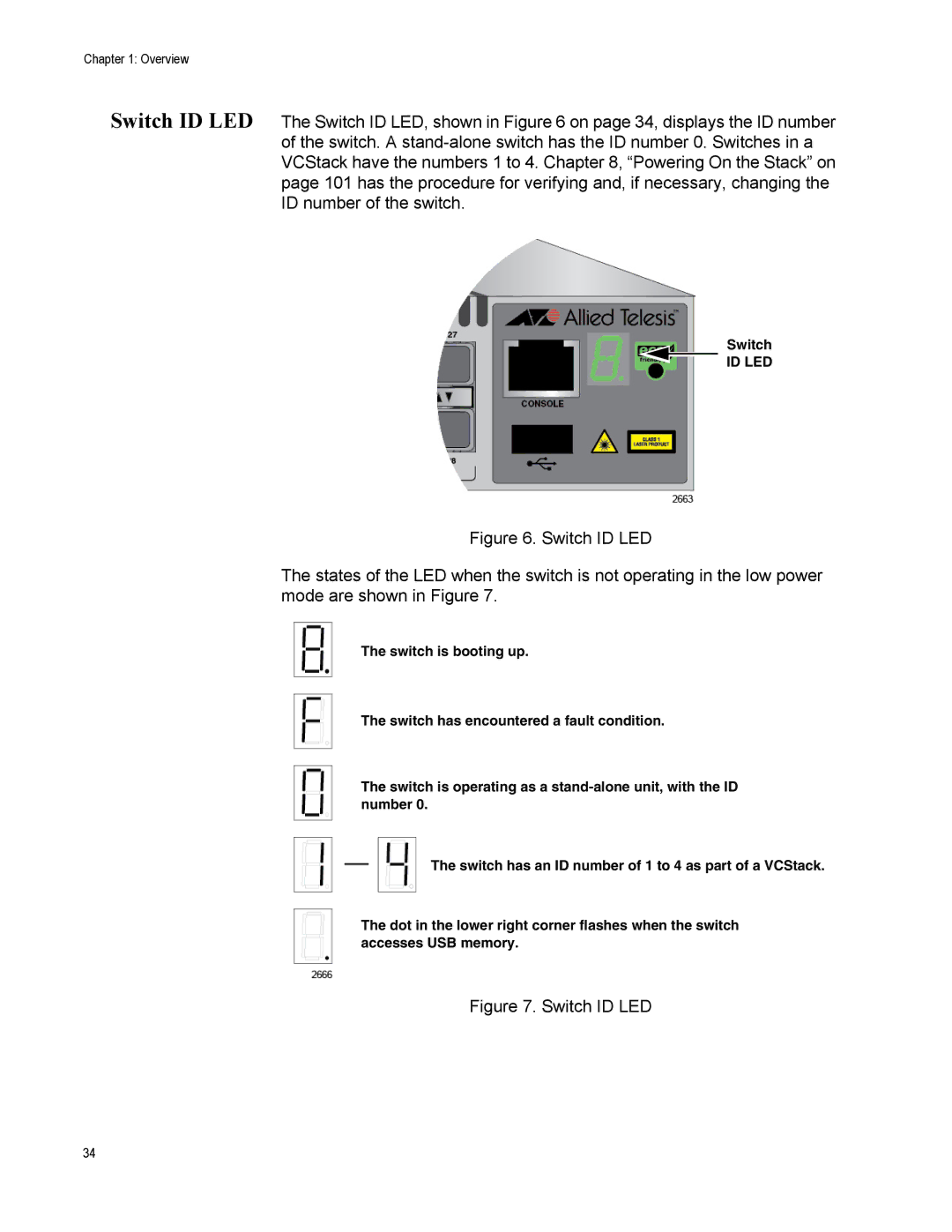
Switch ID LED The Switch ID LED, shown in Figure 6 on page 34, displays the ID number of the switch. A
Switch
ID LED
Figure 6. Switch ID LED
The states of the LED when the switch is not operating in the low power mode are shown in Figure 7.
The switch is booting up.
The switch has encountered a fault condition.
The switch is operating as a
The switch has an ID number of 1 to 4 as part of a VCStack.
The dot in the lower right corner flashes when the switch accesses USB memory.
Figure 7. Switch ID LED
34