Chapter 1: Overview
Note
The
The fan module slots (FAN 1/FAN 2) are for the installation of the
Two
Note
The
Fan LEDs - The fan LEDs FAN 1 (upper LED) / FAN 2 (lower LED) display the status of the fan modules. They are located in the center of the chassis between the fan module slots. See Figure 6 on page 27 for the functional description of these LEDs.
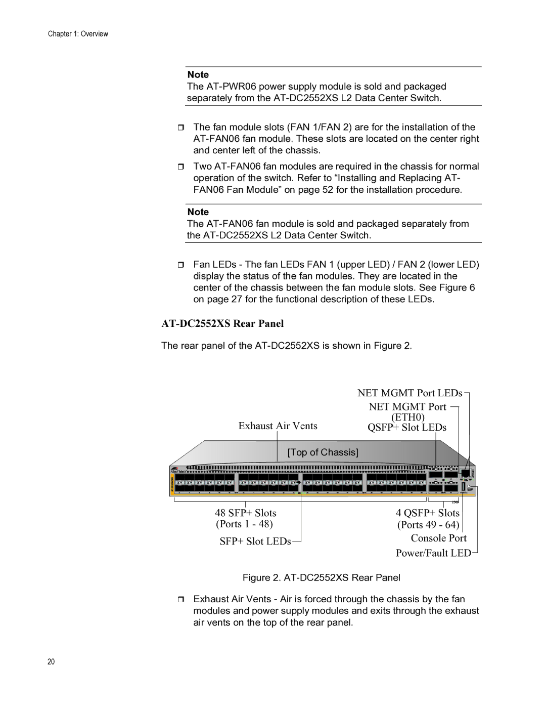
AT-DC2552XS Rear Panel
The rear panel of the
| NET MGMT Port LEDs | ||
| NET MGMT Port |
|
|
|
| ||
Exhaust Air Vents | (ETH0) | ||
QSFP+ Slot LEDs | |||
[Top of Chassis]
48 SFP+ Slots
(Ports 1 - 48)
SFP+ Slot LEDs
4 QSFP+ Slots
(Ports 49 - 64)
Console Port
Power/Fault LED
Figure 2. AT-DC2552XS Rear Panel
Exhaust Air Vents - Air is forced through the chassis by the fan modules and power supply modules and exits through the exhaust air vents on the top of the rear panel.
20