Stack Installation Guide for AT-2552XS L2 Data Center Switch
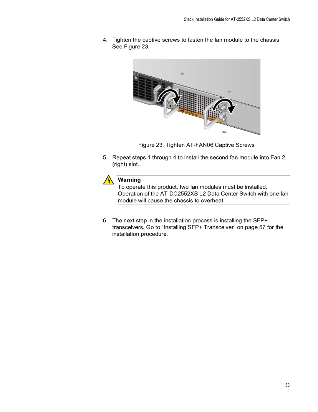
4.Tighten the captive screws to fasten the fan module to the chassis. See Figure 23.
Figure 23. Tighten AT-FAN06 Captive Screws
5.Repeat steps 1 through 4 to install the second fan module into Fan 2 (right) slot.
Warning
To operate this product, two fan modules must be installed. Operation of the AT-DC2552XS L2 Data Center Switch with one fan module will cause the chassis to overheat.
6.The next step in the installation process is installing the SFP+ transceivers. Go to “Installing SFP+ Transceiver” on page 57 for the installation procedure.
53
