Stack Installation Guide for AT-2552XS L2 Data Center Switch
RJ-45 Twisted Pair Port Pinouts
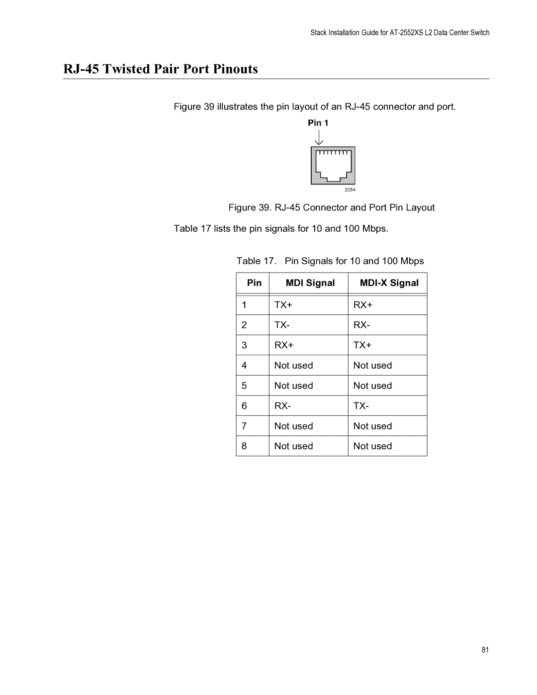
Figure 39 illustrates the pin layout of an RJ-45 connector and port.
Figure 39. RJ-45 Connector and Port Pin Layout
Table 17 lists the pin signals for 10 and 100 Mbps.
Table 17. Pin Signals for 10 and 100 Mbps
Pin | MDI Signal |
|
|
|
|
|
|
|
1 | TX+ | RX+ |
|
|
|
2 | TX- | RX- |
|
|
|
3 | RX+ | TX+ |
|
|
|
4 | Not used | Not used |
|
|
|
5 | Not used | Not used |
|
|
|
6 | RX- | TX- |
|
|
|
7 | Not used | Not used |
|
|
|
8 | Not used | Not used |
|
|
|
81