Stack Installation Guide for AT-2552XS L2 Data Center Switch
Installing the Switch in an Equipment Rack
Note
To install the switch on a desktop, refer to “Installing the Switch on a
Desktop” on page 44.
When installing the
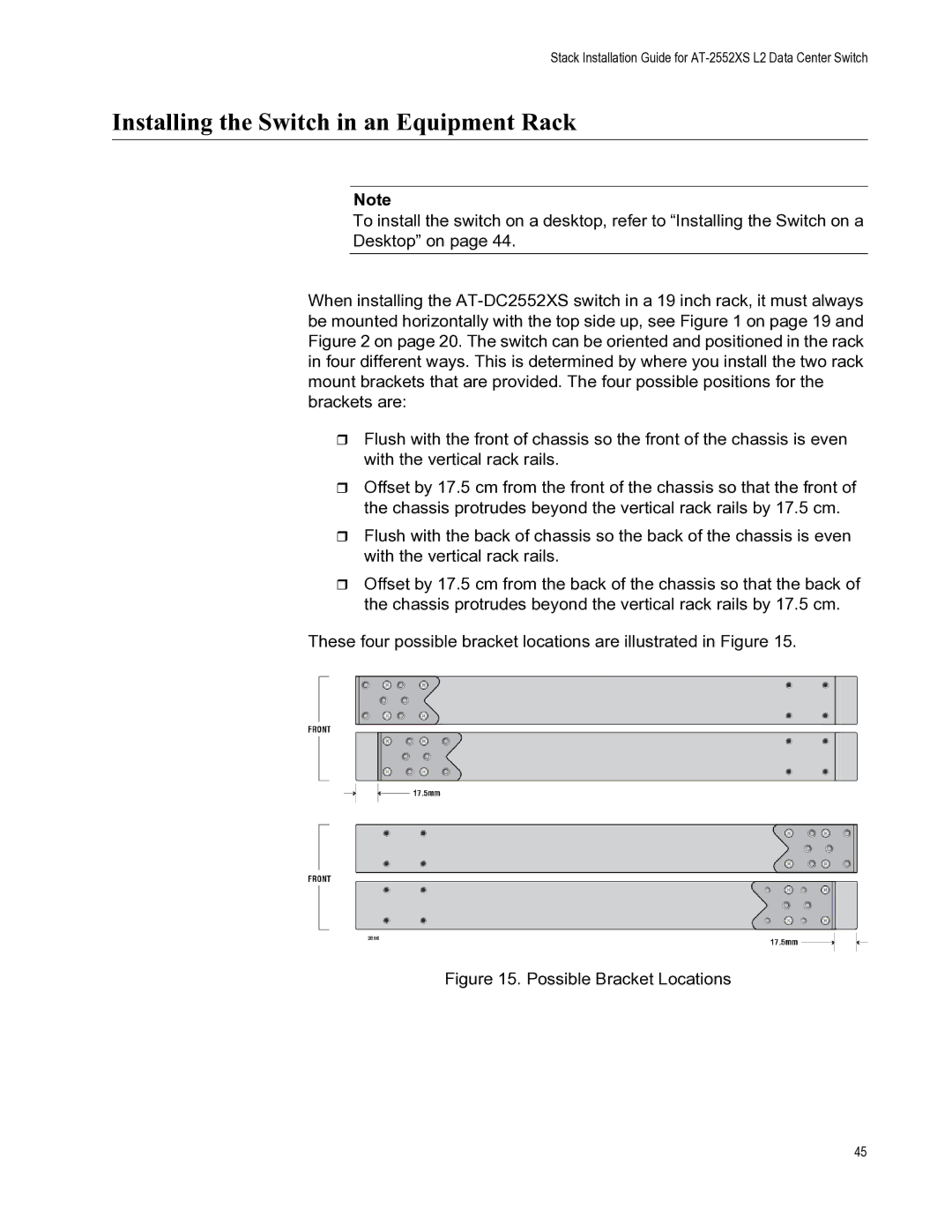
Flush with the front of chassis so the front of the chassis is even with the vertical rack rails.
Offset by 17.5 cm from the front of the chassis so that the front of the chassis protrudes beyond the vertical rack rails by 17.5 cm.
Flush with the back of chassis so the back of the chassis is even with the vertical rack rails.
Offset by 17.5 cm from the back of the chassis so that the back of the chassis protrudes beyond the vertical rack rails by 17.5 cm.
These four possible bracket locations are illustrated in Figure 15.
Figure 15. Possible Bracket Locations
45