Stack Installation Guide for AT-2552XS L2 Data Center Switch
LEDs
Here are the descriptions of the switch’s LEDs.
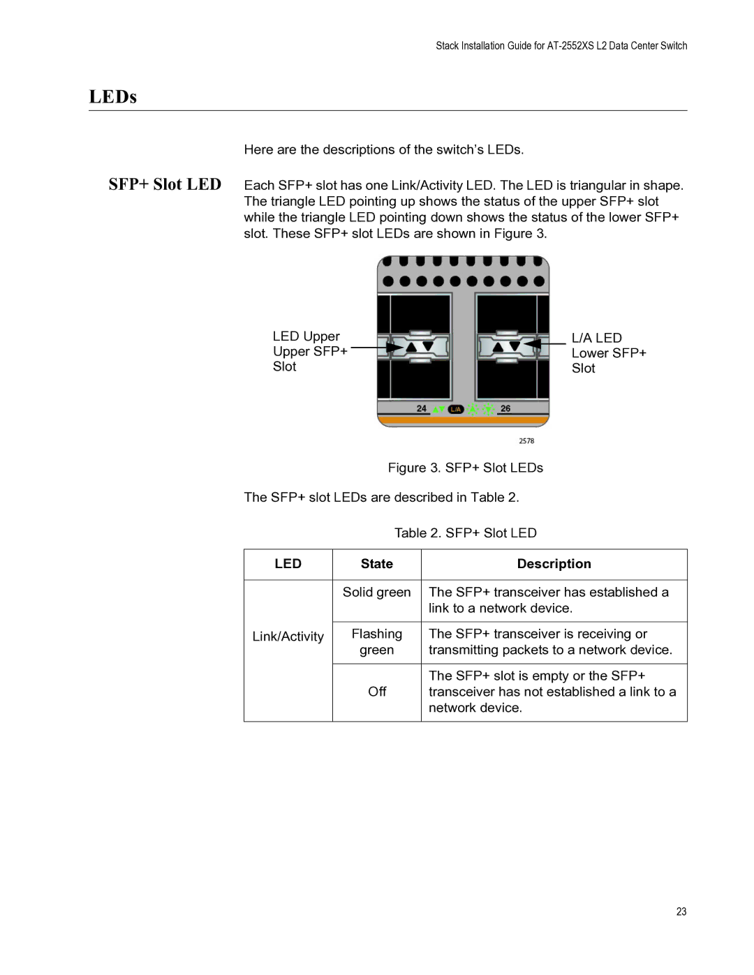
SFP+ Slot LED Each SFP+ slot has one Link/Activity LED. The LED is triangular in shape. The triangle LED pointing up shows the status of the upper SFP+ slot while the triangle LED pointing down shows the status of the lower SFP+ slot. These SFP+ slot LEDs are shown in Figure 3.
LED Upper |
|
|
|
| L/A LED | ||
Upper SFP+ |
|
|
|
|
|
| Lower SFP+ |
|
| ||||||
Slot |
|
|
|
| Slot | ||
Figure 3. SFP+ Slot LEDs
The SFP+ slot LEDs are described in Table 2.
Table 2. SFP+ Slot LED
LED | State | Description |
|
|
|
| Solid green | The SFP+ transceiver has established a |
|
| link to a network device. |
|
|
|
Link/Activity | Flashing | The SFP+ transceiver is receiving or |
| green | transmitting packets to a network device. |
|
|
|
|
| The SFP+ slot is empty or the SFP+ |
| Off | transceiver has not established a link to a |
|
| network device. |
|
|
|
23