Chapter 3: Installing the Switch and Modules
This procedure requires the following items:
Eight bracket screws (included with the switch)
Two equipment rack brackets (included with the switch)
Four standard equipment rack screws (not provided)
Perform this procedure to install the switch in a
Note
If you have installed the rubber feet, remove the rubber feet by prying them off the bottom of the chassis with a
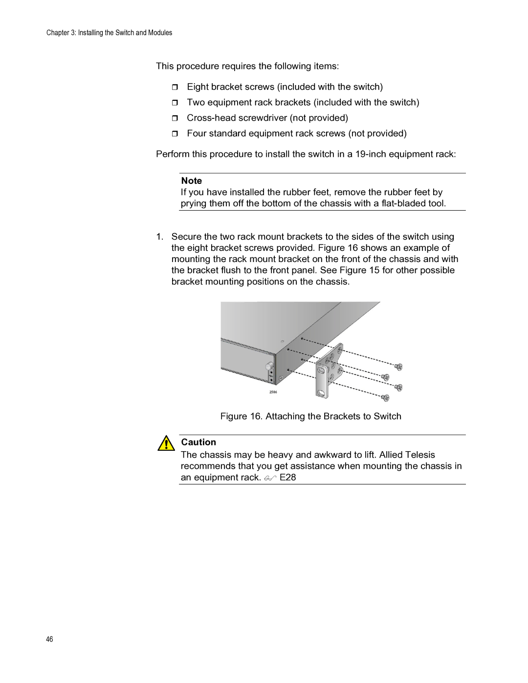
1.Secure the two rack mount brackets to the sides of the switch using the eight bracket screws provided. Figure 16 shows an example of mounting the rack mount bracket on the front of the chassis and with the bracket flush to the front panel. See Figure 15 for other possible bracket mounting positions on the chassis.
Figure 16. Attaching the Brackets to Switch
Caution
The chassis may be heavy and awkward to lift. Allied Telesis recommends that you get assistance when mounting the chassis in an equipment rack. E28
46