Stack Installation Guide for AT-2552XS L2 Data Center Switch
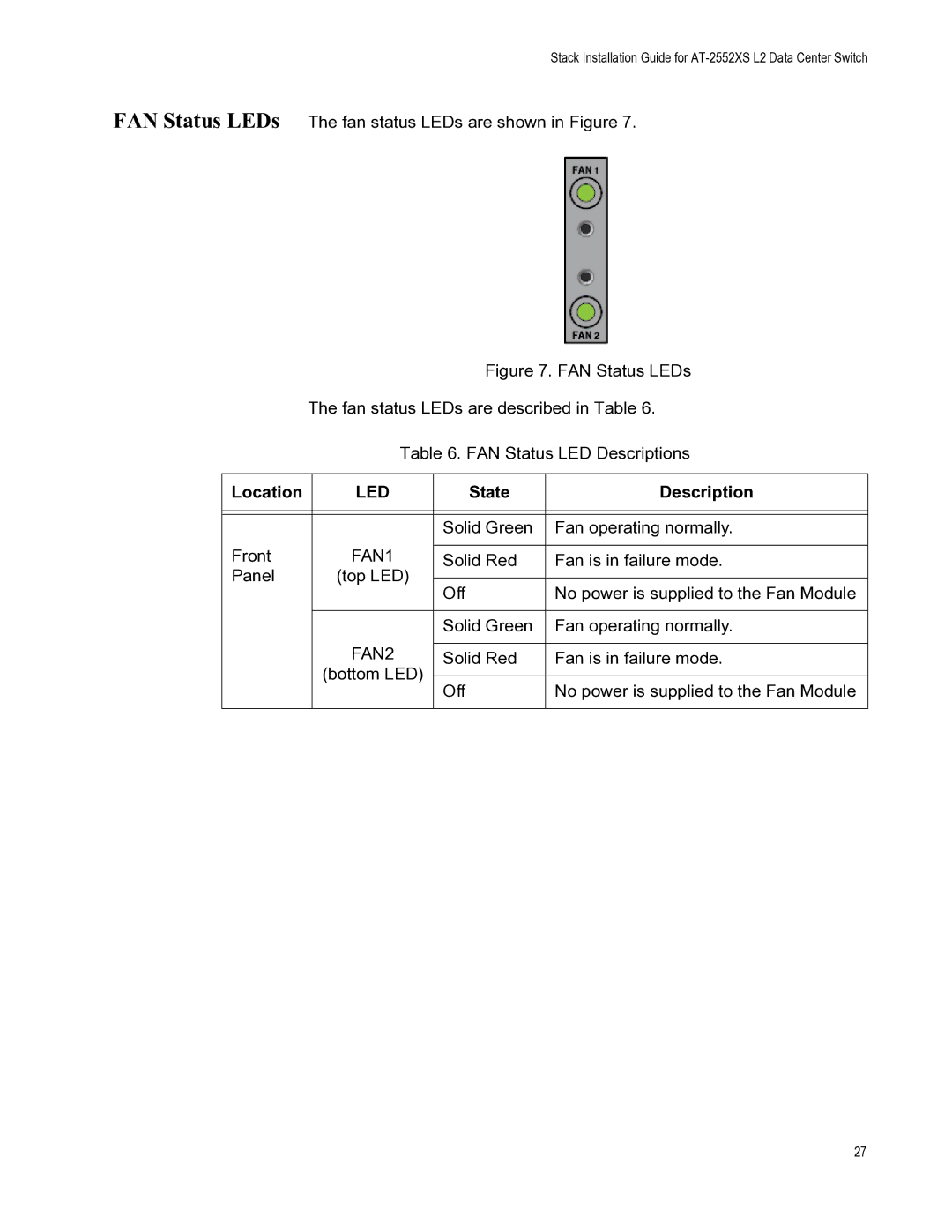
FAN Status LEDs The fan status LEDs are shown in Figure 7.
Figure 7. FAN Status LEDs
The fan status LEDs are described in Table 6.
Table 6. FAN Status LED Descriptions
Location | LED | State | Description | |
|
|
|
| |
|
|
|
| |
|
| Solid Green | Fan operating normally. | |
Front | FAN1 |
|
| |
Solid Red | Fan is in failure mode. | |||
Panel | (top LED) |
|
| |
Off | No power is supplied to the Fan Module | |||
|
| |||
|
|
|
| |
|
| Solid Green | Fan operating normally. | |
| FAN2 |
|
| |
| Solid Red | Fan is in failure mode. | ||
| (bottom LED) |
|
| |
| Off | No power is supplied to the Fan Module | ||
|
| |||
|
|
|
|
27