Rack Assembly
2.Bolt Top Side Subassembly #2 onto Bottom Side Subassembly #2 at same basic hole positions specified in step 1 above. Use (3) M12 x 35 bolts and related hardware: (6) 12mm washers, (3) 12mm lockwashers and (3) M12 nuts. Again, DO NOT bolt REAR hole!
Top Side Subassembly #2
(870-1657A)
Bottom Side Subassembly #2
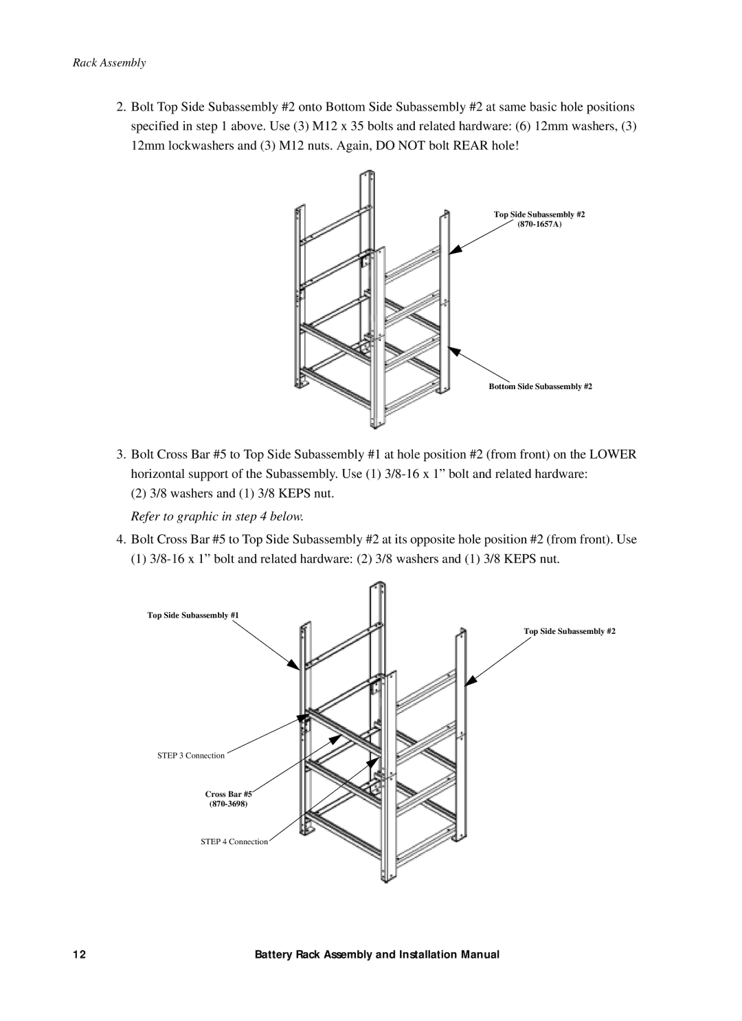
3.Bolt Cross Bar #5 to Top Side Subassembly #1 at hole position #2 (from front) on the LOWER horizontal support of the Subassembly. Use (1)
(2) 3/8 washers and (1) 3/8 KEPS nut.
Refer to graphic in step 4 below.
4.Bolt Cross Bar #5 to Top Side Subassembly #2 at its opposite hole position #2 (from front). Use
(1)
Top Side Subassembly #1
Top Side Subassembly #2
STEP 3 Connection
Cross Bar #5
STEP 4 Connection
12 | Battery Rack Assembly and Installation Manual |