Appendix C: Employing Sidecars
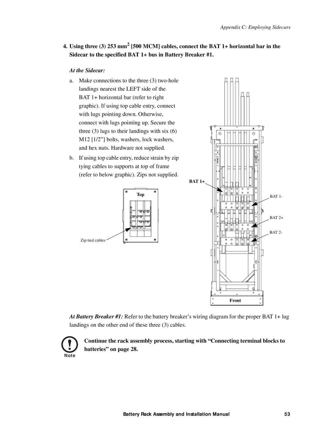
4.Using three (3) 253 mm2 [500 MCM] cables, connect the BAT 1+ horizontal bar in the Sidecar to the specified BAT 1+ bus in Battery Breaker #1.
At the Sidecar:
a.Make connections to the three (3)
b.If using top cable entry, reduce strain by zip tying cables to supports at top of frame (refer to below graphic). Zips not supplied.
BAT 1+
Top
Zip tied cables ![]()
BAT 1-
BAT 2+
BAT 2-
Front
At Battery Breaker #1: Refer to the battery breaker’s wiring diagram for the proper BAT 1+ lug landings on the other end of these three (3) cables.
Continue the rack assembly process, starting with “Connecting terminal blocks to batteries” on page 28.
Note
Battery Rack Assembly and Installation Manual | 53 |
