Rack Assembly
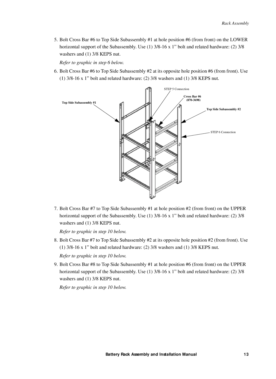
5.Bolt Cross Bar #6 to Top Side Subassembly #1 at hole position #6 (from front) on the LOWER horizontal support of the Subassembly. Use (1)
Refer to graphic in step 6 below.
6.Bolt Cross Bar #6 to Top Side Subassembly #2 at its opposite hole position #6 (from front). Use
(1)
STEP 5 Connection
Top Side Subassembly #1
Cross Bar #6 (870-3698)
Top Side Subassembly #2
STEP 6 Connection
7.Bolt Cross Bar #7 to Top Side Subassembly #1 at hole position #2 (from front) on the UPPER horizontal support of the Subassembly. Use (1)
Refer to graphic in step 10 below.
8.Bolt Cross Bar #7 to Top Side Subassembly #2 at its opposite hole position #2 (from front). Use
(1)
Refer to graphic in step 10 below.
9.Bolt Cross Bar #8 to Top Side Subassembly #1 at hole position #6 (from front) on the UPPER horizontal support of the Subassembly. Use (1)
Refer to graphic in step 10 below.
Battery Rack Assembly and Installation Manual | 13 |