Rack Assembly
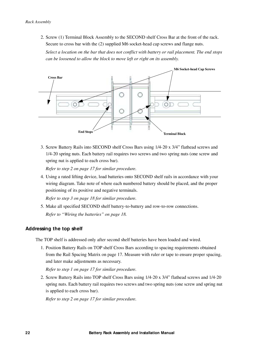
2.Screw (1) Terminal Block Assembly to the SECOND shelf Cross Bar at the front of the rack. Secure to cross bar with the (2) supplied M6
Select a location on the bar that does not conflict with battery or rail placement. The end stops can be loosened to allow the block to move left or right on its assembly.
M6
Cross Bar
TERMINAL t
TER |
| t |
|
| |
TERMINAL |
|
|
TER | End Stops | Terminal Block |
| ||
|
|
3.Screw Battery Rails into SECOND shelf Cross Bars using
Refer to step 2 on page 17 for similar procedure.
4.Using a rated lifting device, load batteries onto SECOND shelf rails in accordance with your wiring diagram. Take note of where each numbered battery should be placed, and the proper positioning of its positive and negative terminals.
Refer to step 3 on page 18 for similar procedure.
5.Make all specified SECOND shelf
Addressing the top shelf
The TOP shelf is addressed only after second shelf batteries have been loaded and wired.
1.Position Battery Rails on TOP shelf Cross Bars according to spacing requirements obtained from the Rail Spacing Matrix on page 17. Measure with ruler or tape to ensure proper spacing, and later make adjustments as necessary.
Refer to step 1 on page 17 for similar procedure.
2.Screw Battery Rails into TOP shelf Cross Bars using
Refer to step 2 on page 17 for similar procedure.
22 | Battery Rack Assembly and Installation Manual |