Chapter 3Signals and Pinout Tables
Table
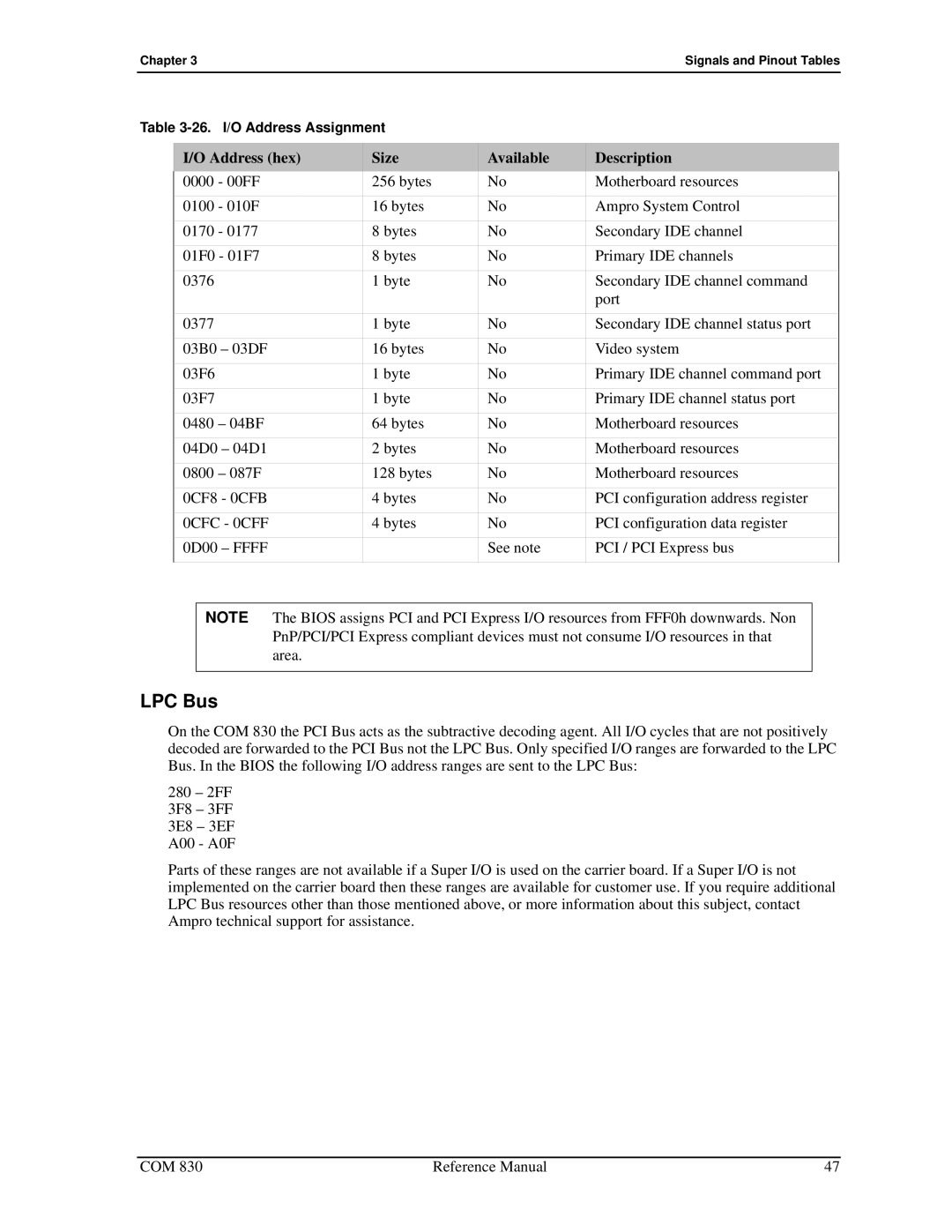
I/O Address (hex) | Size | Available | Description | |||
0000 | - 00FF | 256 bytes | No | Motherboard resources | ||
0100 | - 010F | 16 bytes | No | Ampro System Control | ||
0170 | - 0177 | 8 bytes | No | Secondary IDE channel | ||
01F0 - 01F7 | 8 bytes | No | Primary IDE channels | |||
0376 |
| 1 byte | No | Secondary IDE channel command | ||
|
|
|
|
| port | |
0377 |
| 1 byte | No | Secondary IDE channel status port | ||
03B0 – 03DF | 16 bytes | No | Video system | |||
03F6 |
| 1 byte | No | Primary IDE channel command port | ||
03F7 |
| 1 byte | No | Primary IDE channel status port | ||
0480 | – 04BF | 64 bytes | No | Motherboard resources | ||
04D0 – 04D1 | 2 bytes | No | Motherboard resources | |||
0800 | – 087F | 128 bytes | No | Motherboard resources | ||
0CF8 - 0CFB | 4 bytes | No | PCI configuration address register | |||
0CFC - 0CFF | 4 bytes | No | PCI configuration data register | |||
0D00 – FFFF |
| See note | PCI / PCI Express bus | |||
|
|
| ||||
| NOTE The BIOS assigns PCI and PCI Express I/O resources from FFF0h downwards. Non |
| ||||
|
| PnP/PCI/PCI Express compliant devices must not consume I/O resources in that |
| |||
|
| area. |
|
|
|
|
|
|
|
|
|
|
|
LPC Bus
On the COM 830 the PCI Bus acts as the subtractive decoding agent. All I/O cycles that are not positively decoded are forwarded to the PCI Bus not the LPC Bus. Only specified I/O ranges are forwarded to the LPC Bus. In the BIOS the following I/O address ranges are sent to the LPC Bus:
280 – 2FF
3F8 – 3FF
3E8 – 3EF
A00 - A0F
Parts of these ranges are not available if a Super I/O is used on the carrier board. If a Super I/O is not implemented on the carrier board then these ranges are available for customer use. If you require additional LPC Bus resources other than those mentioned above, or more information about this subject, contact Ampro technical support for assistance.
COM 830 | Reference Manual | 47 |