Chapter 3 |
|
| Signals and Pinout Tables | |||
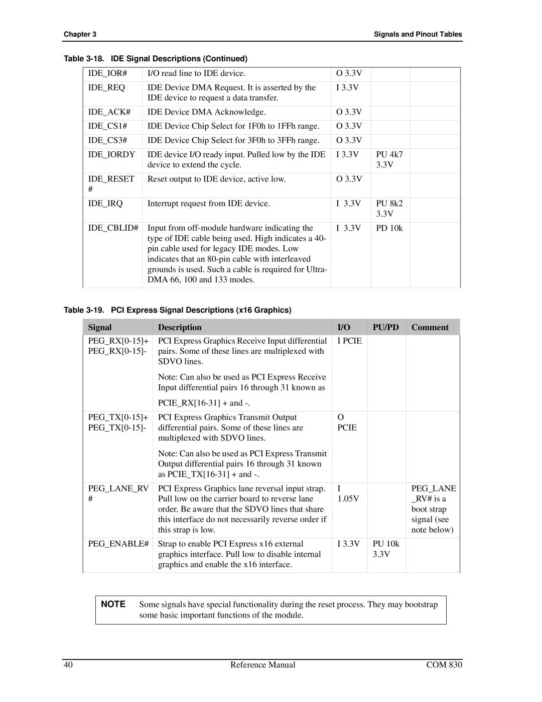
Table |
|
|
|
| ||
|
|
|
|
|
|
|
| IDE_IOR# | I/O read line to IDE device. | O 3.3V |
|
|
|
| IDE_REQ | IDE Device DMA Request. It is asserted by the | I 3.3V |
|
|
|
|
| IDE device to request a data transfer. |
|
|
|
|
| IDE_ACK# | IDE Device DMA Acknowledge. | O 3.3V |
|
|
|
| IDE_CS1# | IDE Device Chip Select for 1F0h to 1FFh range. | O 3.3V |
|
|
|
| IDE_CS3# | IDE Device Chip Select for 3F0h to 3FFh range. | O 3.3V |
|
|
|
| IDE_IORDY | IDE device I/O ready input. Pulled low by the IDE | I 3.3V | PU 4k7 |
|
|
|
| device to extend the cycle. |
| 3.3V |
|
|
| IDE_RESET | Reset output to IDE device, active low. | O 3.3V |
|
|
|
| # |
|
|
|
|
|
| IDE_IRQ | Interrupt request from IDE device. | I 3.3V | PU 8k2 |
|
|
|
|
|
| 3.3V |
|
|
| IDE_CBLID# | Input from | I 3.3V | PD 10k |
|
|
|
| type of IDE cable being used. High indicates a 40- |
|
|
|
|
|
| pin cable used for legacy IDE modes. Low |
|
|
|
|
|
| indicates that an |
|
|
|
|
|
| grounds is used. Such a cable is required for Ultra- |
|
|
|
|
|
| DMA 66, 100 and 133 modes. |
|
|
|
|
|
|
|
|
|
|
|
Table
Signal | Description | I/O | PU/PD | Comment |
PCI Express Graphics Receive Input differential | I PCIE |
|
| |
pairs. Some of these lines are multiplexed with |
|
|
| |
| SDVO lines. |
|
|
|
| Note: Can also be used as PCI Express Receive |
|
|
|
| Input differential pairs 16 through 31 known as |
|
|
|
|
|
|
| |
|
|
|
|
|
PCI Express Graphics Transmit Output | O |
|
| |
differential pairs. Some of these lines are | PCIE |
|
| |
| multiplexed with SDVO lines. |
|
|
|
| Note: Can also be used as PCI Express Transmit |
|
|
|
| Output differential pairs 16 through 31 known |
|
|
|
| as |
|
|
|
PEG_LANE_RV | PCI Express Graphics lane reversal input strap. | I |
| PEG_LANE |
# | Pull low on the carrier board to reverse lane | 1.05V |
| _RV# is a |
| order. Be aware that the SDVO lines that share |
|
| boot strap |
| this interface do not necessarily reverse order if |
|
| signal (see |
| this strap is low. |
|
| note below) |
PEG_ENABLE# | Strap to enable PCI Express x16 external | I 3.3V | PU 10k |
|
| graphics interface. Pull low to disable internal |
| 3.3V |
|
| graphics and enable the x16 interface. |
|
|
|
|
|
|
|
|
NOTE Some signals have special functionality during the reset process. They may bootstrap some basic important functions of the module.
40 | Reference Manual | COM 830 |