Chapter 3 |
|
|
|
| Signals and Pinout Tables | ||||
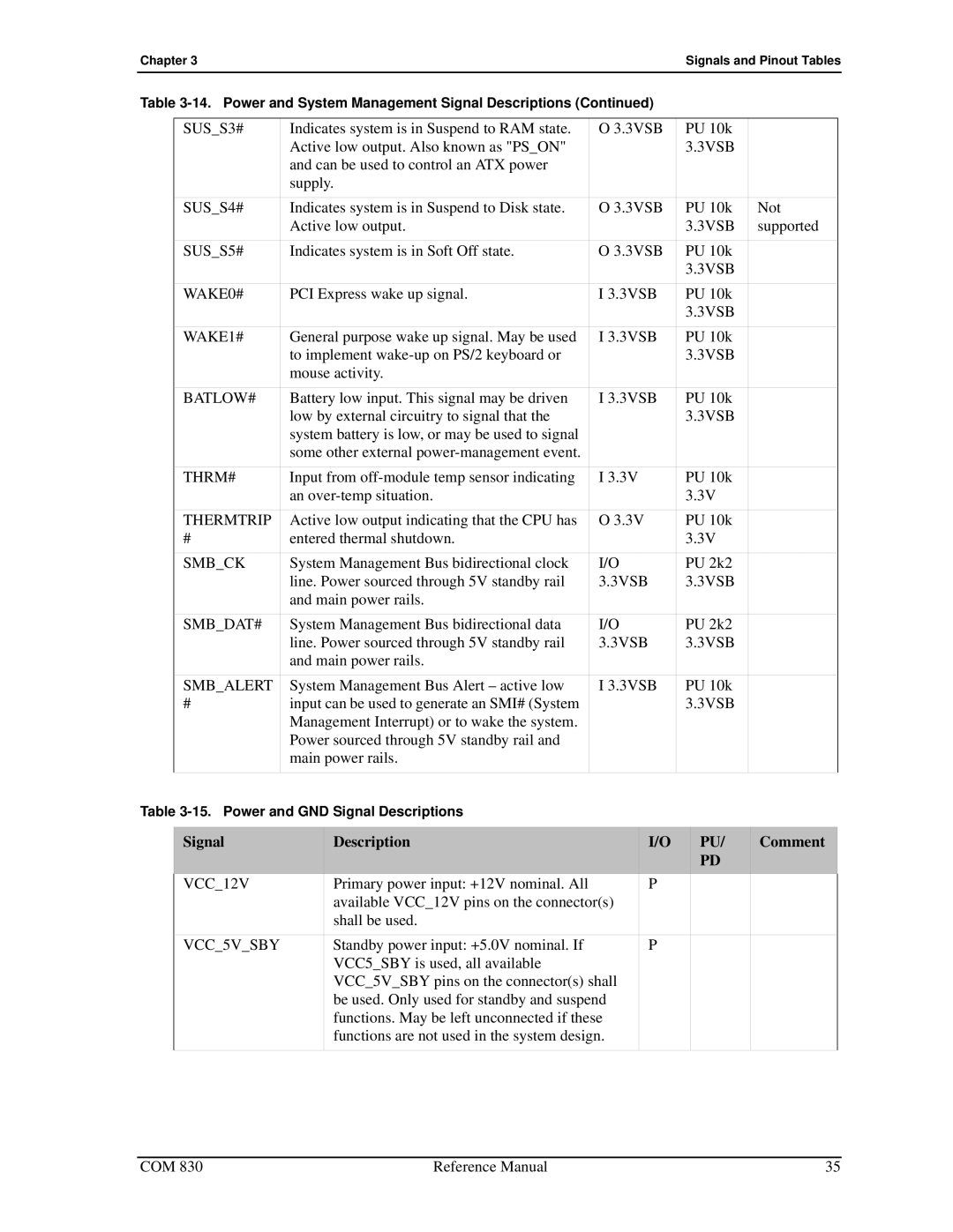
Table |
|
|
|
| |||||
|
|
|
|
|
|
|
|
|
|
| SUS_S3# | Indicates system is in Suspend to RAM state. | O 3.3VSB | PU 10k |
|
| |||
|
| Active low output. Also known as "PS_ON" |
|
| 3.3VSB |
|
| ||
|
| and can be used to control an ATX power |
|
|
|
|
|
| |
|
| supply. |
|
|
|
|
|
| |
| SUS_S4# | Indicates system is in Suspend to Disk state. | O 3.3VSB | PU 10k | Not |
| |||
|
| Active low output. |
|
| 3.3VSB | supported |
| ||
| SUS_S5# | Indicates system is in Soft Off state. | O 3.3VSB | PU 10k |
|
| |||
|
|
|
|
|
| 3.3VSB |
|
| |
| WAKE0# | PCI Express wake up signal. | I 3.3VSB | PU 10k |
|
| |||
|
|
|
|
|
| 3.3VSB |
|
| |
| WAKE1# | General purpose wake up signal. May be used | I 3.3VSB | PU 10k |
|
| |||
|
| to implement |
|
| 3.3VSB |
|
| ||
|
| mouse activity. |
|
|
|
|
|
| |
| BATLOW# | Battery low input. This signal may be driven | I 3.3VSB | PU 10k |
|
| |||
|
| low by external circuitry to signal that the |
|
| 3.3VSB |
|
| ||
|
| system battery is low, or may be used to signal |
|
|
|
|
|
| |
|
| some other external |
|
|
|
|
|
| |
| THRM# | Input from | I 3.3V | PU 10k |
|
| |||
|
| an |
|
| 3.3V |
|
| ||
| THERMTRIP | Active low output indicating that the CPU has | O 3.3V | PU 10k |
|
| |||
| # | entered thermal shutdown. |
|
| 3.3V |
|
| ||
| SMB_CK | System Management Bus bidirectional clock | I/O | PU 2k2 |
|
| |||
|
| line. Power sourced through 5V standby rail | 3.3VSB | 3.3VSB |
|
| |||
|
| and main power rails. |
|
|
|
|
|
| |
| SMB_DAT# | System Management Bus bidirectional data | I/O | PU 2k2 |
|
| |||
|
| line. Power sourced through 5V standby rail | 3.3VSB | 3.3VSB |
|
| |||
|
| and main power rails. |
|
|
|
|
|
| |
| SMB_ALERT | System Management Bus Alert – active low | I 3.3VSB | PU 10k |
|
| |||
| # | input can be used to generate an SMI# (System |
|
| 3.3VSB |
|
| ||
|
| Management Interrupt) or to wake the system. |
|
|
|
|
|
| |
|
| Power sourced through 5V standby rail and |
|
|
|
|
|
| |
|
| main power rails. |
|
|
|
|
|
| |
|
|
|
|
|
|
|
|
|
|
Table |
|
|
|
|
|
| |||
|
|
|
|
|
|
|
|
|
|
| Signal |
| Description |
| I/O |
| PU/ | Comment |
|
|
|
|
|
|
|
| PD |
|
|
| VCC_12V |
| Primary power input: +12V nominal. All |
| P |
|
|
|
|
|
|
| available VCC_12V pins on the connector(s) |
|
|
|
|
| |
|
|
| shall be used. |
|
|
|
|
|
|
| VCC_5V_SBY |
| Standby power input: +5.0V nominal. If |
| P |
|
|
|
|
|
|
| VCC5_SBY is used, all available |
|
|
|
|
|
|
|
|
| VCC_5V_SBY pins on the connector(s) shall |
|
|
|
|
| |
|
|
| be used. Only used for standby and suspend |
|
|
|
|
| |
|
|
| functions. May be left unconnected if these |
|
|
|
|
| |
|
|
| functions are not used in the system design. |
|
|
|
|
| |
|
|
|
|
|
|
|
|
|
|
COM 830 | Reference Manual | 35 |