Chapter 3Signals and Pinout Tables
A-B Connector Signal Descriptions
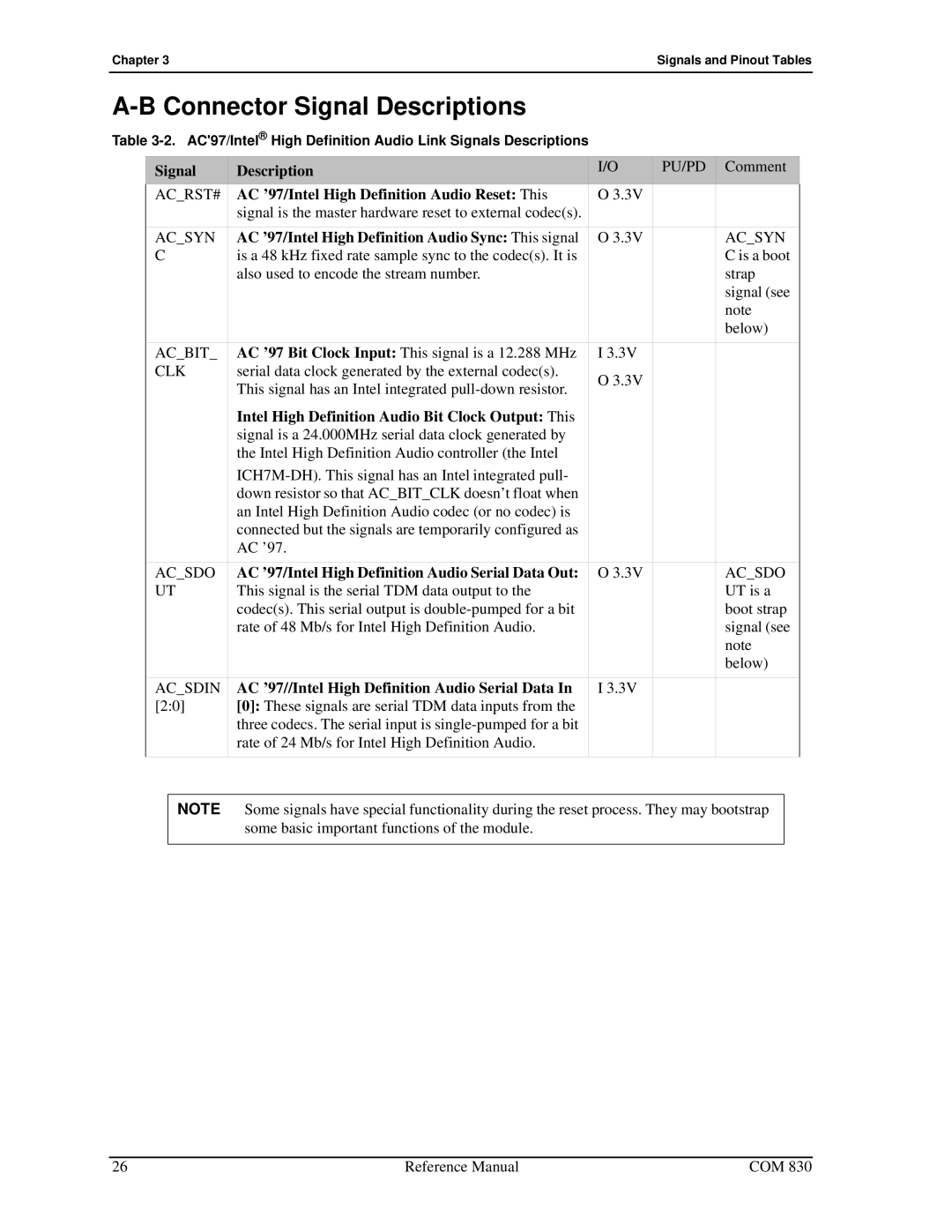
Table
Signal | Description | I/O | PU/PD | Comment |
AC_RST# | AC ’97/Intel High Definition Audio Reset: This | O 3.3V |
|
|
| signal is the master hardware reset to external codec(s). |
|
|
|
AC_SYN | AC ’97/Intel High Definition Audio Sync: This signal | O 3.3V |
| AC_SYN |
C | is a 48 kHz fixed rate sample sync to the codec(s). It is |
|
| C is a boot |
| also used to encode the stream number. |
|
| strap |
|
|
|
| signal (see |
|
|
|
| note |
|
|
|
| below) |
AC_BIT_ | AC ’97 Bit Clock Input: This signal is a 12.288 MHz | I 3.3V |
|
|
CLK | serial data clock generated by the external codec(s). | O 3.3V |
|
|
| This signal has an Intel integrated |
|
| |
|
|
|
| |
| Intel High Definition Audio Bit Clock Output: This |
|
|
|
| signal is a 24.000MHz serial data clock generated by |
|
|
|
| the Intel High Definition Audio controller (the Intel |
|
|
|
|
|
|
| |
| down resistor so that AC_BIT_CLK doesn’t float when |
|
|
|
| an Intel High Definition Audio codec (or no codec) is |
|
|
|
| connected but the signals are temporarily configured as |
|
|
|
| AC ’97. |
|
|
|
AC_SDO | AC ’97/Intel High Definition Audio Serial Data Out: | O 3.3V |
| AC_SDO |
UT | This signal is the serial TDM data output to the |
|
| UT is a |
| codec(s). This serial output is |
|
| boot strap |
| rate of 48 Mb/s for Intel High Definition Audio. |
|
| signal (see |
|
|
|
| note |
|
|
|
| below) |
AC_SDIN | AC ’97//Intel High Definition Audio Serial Data In | I 3.3V |
|
|
[2:0] | [0]: These signals are serial TDM data inputs from the |
|
|
|
| three codecs. The serial input is |
|
|
|
| rate of 24 Mb/s for Intel High Definition Audio. |
|
|
|
|
|
|
|
|
NOTE Some signals have special functionality during the reset process. They may bootstrap some basic important functions of the module.
26 | Reference Manual | COM 830 |