Chapter 3 |
|
| Signals and Pinout Tables | ||
Table |
|
|
| ||
|
|
|
|
|
|
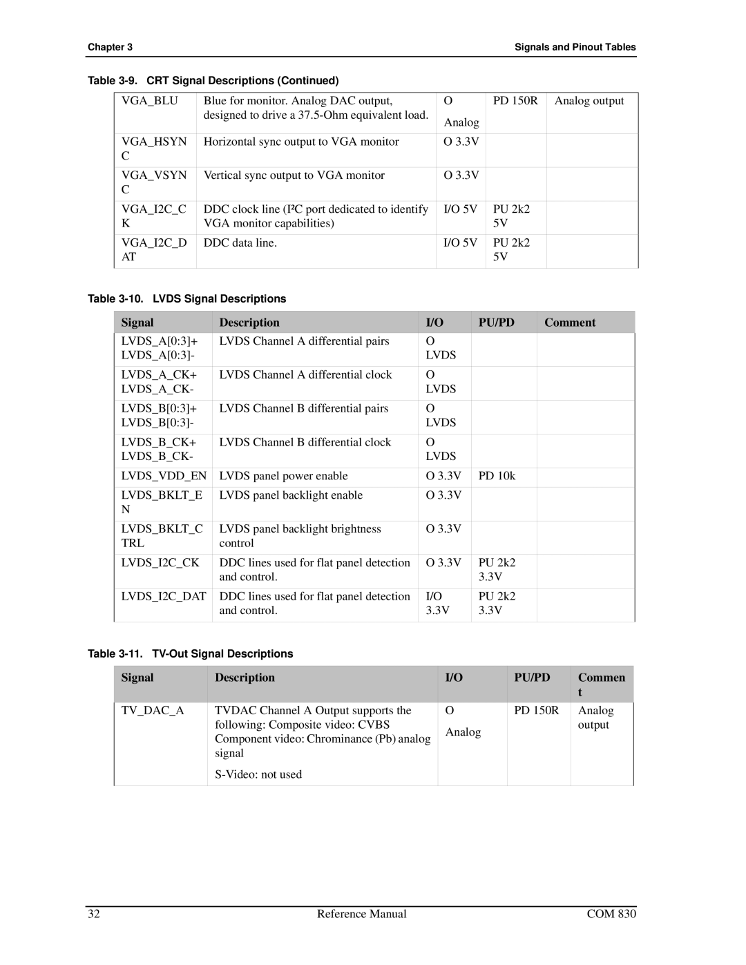
| VGA_BLU | Blue for monitor. Analog DAC output, | O | PD 150R | Analog output |
|
| designed to drive a | Analog |
|
|
|
|
|
|
| |
|
|
|
|
|
|
| VGA_HSYN | Horizontal sync output to VGA monitor | O 3.3V |
|
|
| C |
|
|
|
|
| VGA_VSYN | Vertical sync output to VGA monitor | O 3.3V |
|
|
| C |
|
|
|
|
| VGA_I2C_C | DDC clock line (I²C port dedicated to identify | I/O 5V | PU 2k2 |
|
| K | VGA monitor capabilities) |
| 5V |
|
| VGA_I2C_D | DDC data line. | I/O 5V | PU 2k2 |
|
| AT |
|
| 5V |
|
|
|
|
|
|
|
Table
Signal | Description | I/O | PU/PD | Comment |
LVDS_A[0:3]+ | LVDS Channel A differential pairs | O |
|
|
LVDS_A[0:3]- |
| LVDS |
|
|
LVDS_A_CK+ | LVDS Channel A differential clock | O |
|
|
LVDS_A_CK- |
| LVDS |
|
|
LVDS_B[0:3]+ | LVDS Channel B differential pairs | O |
|
|
LVDS_B[0:3]- |
| LVDS |
|
|
LVDS_B_CK+ | LVDS Channel B differential clock | O |
|
|
LVDS_B_CK- |
| LVDS |
|
|
LVDS_VDD_EN | LVDS panel power enable | O 3.3V | PD 10k |
|
LVDS_BKLT_E | LVDS panel backlight enable | O 3.3V |
|
|
N |
|
|
|
|
LVDS_BKLT_C | LVDS panel backlight brightness | O 3.3V |
|
|
TRL | control |
|
|
|
LVDS_I2C_CK | DDC lines used for flat panel detection | O 3.3V | PU 2k2 |
|
| and control. |
| 3.3V |
|
LVDS_I2C_DAT | DDC lines used for flat panel detection | I/O | PU 2k2 |
|
| and control. | 3.3V | 3.3V |
|
|
|
|
|
|
Table
Signal | Description | I/O | PU/PD | Commen |
|
|
|
| t |
TV_DAC_A | TVDAC Channel A Output supports the | O | PD 150R | Analog |
| following: Composite video: CVBS | Analog |
| output |
| Component video: Chrominance (Pb) analog |
|
| |
|
|
|
| |
| signal |
|
|
|
|
|
|
| |
|
|
|
|
|
32 | Reference Manual | COM 830 |