Chapter 3Signals and Pinout Tables
Table
| Table3- | 32. |
|
|
|
|
|
|
|
|
|
|
|
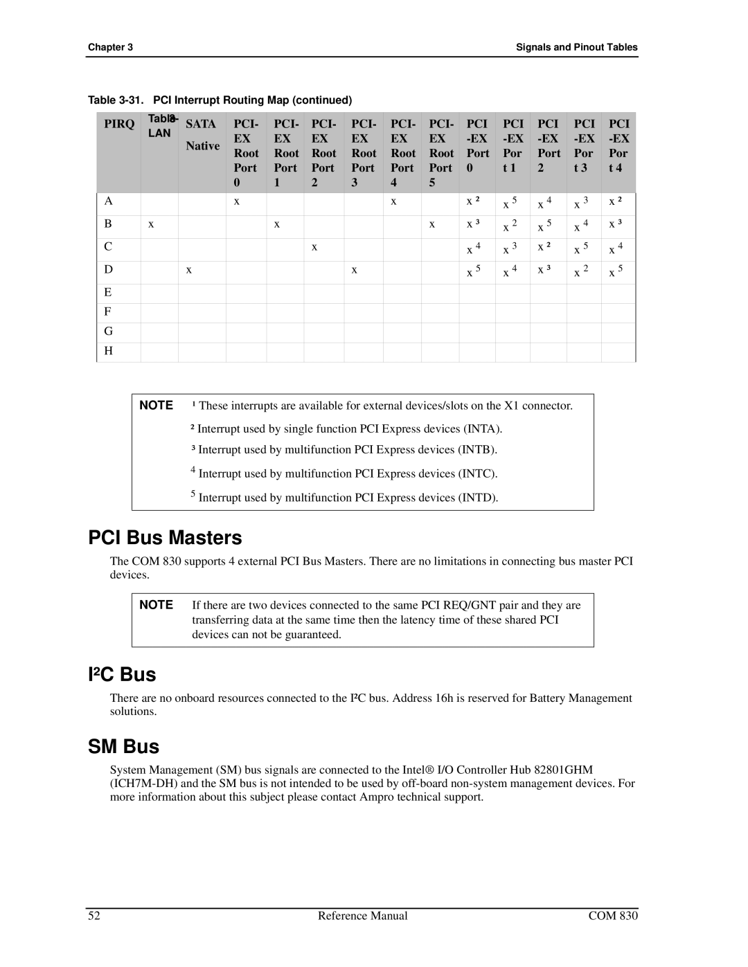
PIRQ | LAN | SATA | PCI- | PCI- | PCI- | PCI- | PCI- | PCI- | PCI | PCI | PCI | PCI | PCI |
|
| Native | EX | EX | EX | EX | EX | EX | |||||
|
| Root | Root | Root | Root | Root | Root | Port | Por | Port | Por | Por | |
|
|
| |||||||||||
|
|
| Port | Port | Port | Port | Port | Port | 0 | t 1 | 2 | t 3 | t 4 |
|
|
| 0 | 1 | 2 | 3 | 4 | 5 |
|
|
|
|
|
A |
|
| x |
|
|
| x |
| x ² | x 5 | x 4 | x 3 | x ² |
B | x |
|
| x |
|
|
| x | x ³ | x 2 | x 5 | x 4 | x ³ |
C |
|
|
|
| x |
|
|
| x 4 | x 3 | x ² | x 5 | x 4 |
D |
| x |
|
|
| x |
|
| x 5 | x 4 | x ³ | x 2 | x 5 |
E |
|
|
|
|
|
|
|
|
|
|
|
|
|
F |
|
|
|
|
|
|
|
|
|
|
|
|
|
G |
|
|
|
|
|
|
|
|
|
|
|
|
|
H |
|
|
|
|
|
|
|
|
|
|
|
|
|
|
|
|
|
|
|
|
|
|
|
|
|
|
|
NOTE ¹ These interrupts are available for external devices/slots on the X1 connector.
²Interrupt used by single function PCI Express devices (INTA).
³Interrupt used by multifunction PCI Express devices (INTB).
4Interrupt used by multifunction PCI Express devices (INTC).
5Interrupt used by multifunction PCI Express devices (INTD).
PCI Bus Masters
The COM 830 supports 4 external PCI Bus Masters. There are no limitations in connecting bus master PCI devices.
NOTE If there are two devices connected to the same PCI REQ/GNT pair and they are transferring data at the same time then the latency time of these shared PCI devices can not be guaranteed.
I²C Bus
There are no onboard resources connected to the I²C bus. Address 16h is reserved for Battery Management solutions.
SM Bus
System Management (SM) bus signals are connected to the Intel® I/O Controller Hub 82801GHM
52 | Reference Manual | COM 830 |