Chapter 3 Signals and Pinout Tables
The following section describes the signals found on COM Express™ Type II connectors used for Ampro modules.
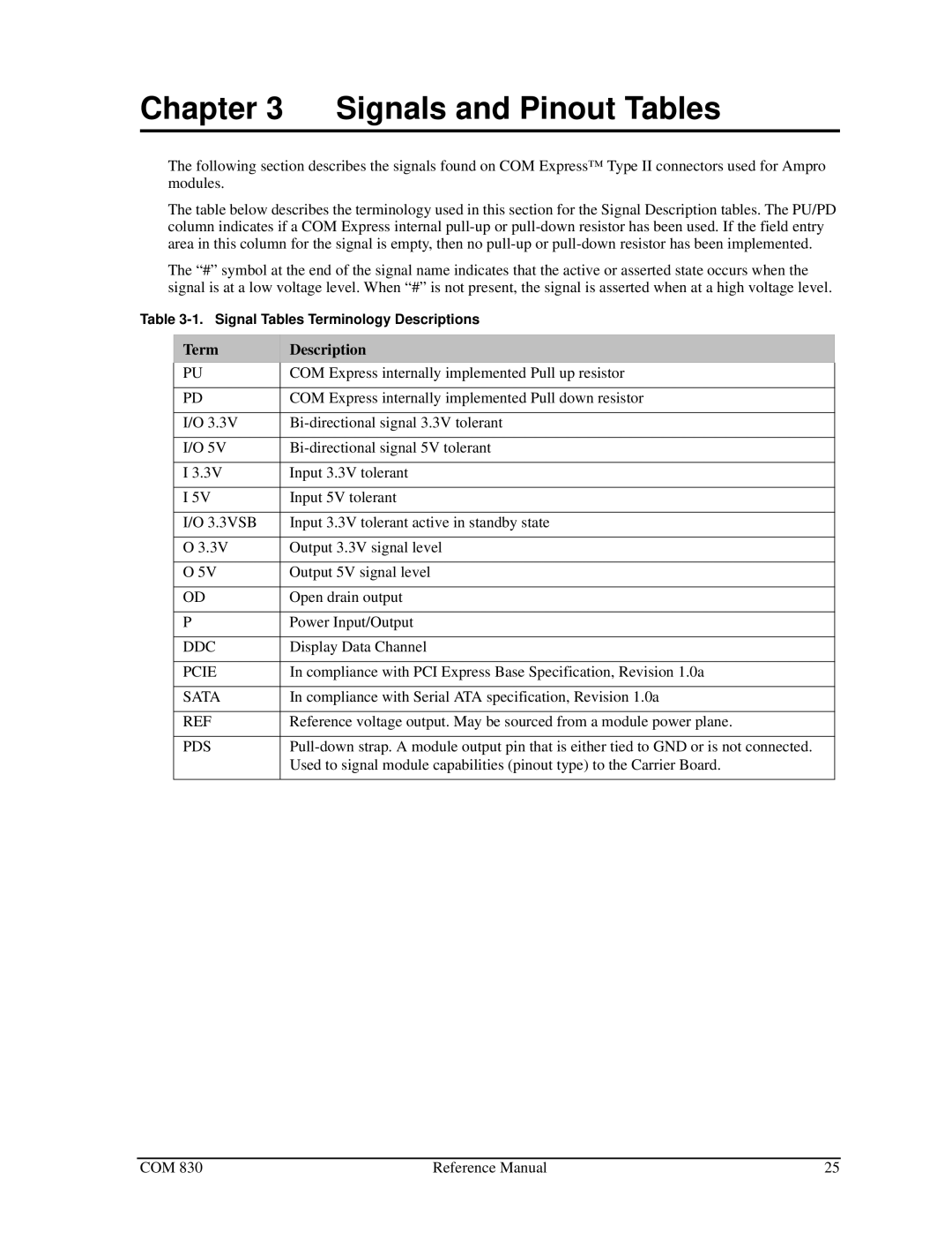
The table below describes the terminology used in this section for the Signal Description tables. The PU/PD column indicates if a COM Express internal
The “#” symbol at the end of the signal name indicates that the active or asserted state occurs when the signal is at a low voltage level. When “#” is not present, the signal is asserted when at a high voltage level.
Table
Term | Description |
PU | COM Express internally implemented Pull up resistor |
|
|
PD | COM Express internally implemented Pull down resistor |
|
|
I/O 3.3V | |
|
|
I/O 5V | |
|
|
I 3.3V | Input 3.3V tolerant |
|
|
I 5V | Input 5V tolerant |
|
|
I/O 3.3VSB | Input 3.3V tolerant active in standby state |
|
|
O 3.3V | Output 3.3V signal level |
|
|
O 5V | Output 5V signal level |
|
|
OD | Open drain output |
|
|
P | Power Input/Output |
|
|
DDC | Display Data Channel |
|
|
PCIE | In compliance with PCI Express Base Specification, Revision 1.0a |
|
|
SATA | In compliance with Serial ATA specification, Revision 1.0a |
|
|
REF | Reference voltage output. May be sourced from a module power plane. |
|
|
PDS | |
| Used to signal module capabilities (pinout type) to the Carrier Board. |
|
|
COM 830 | Reference Manual | 25 |