Chapter 3 |
|
|
|
| Signals and Pinout Tables | |||
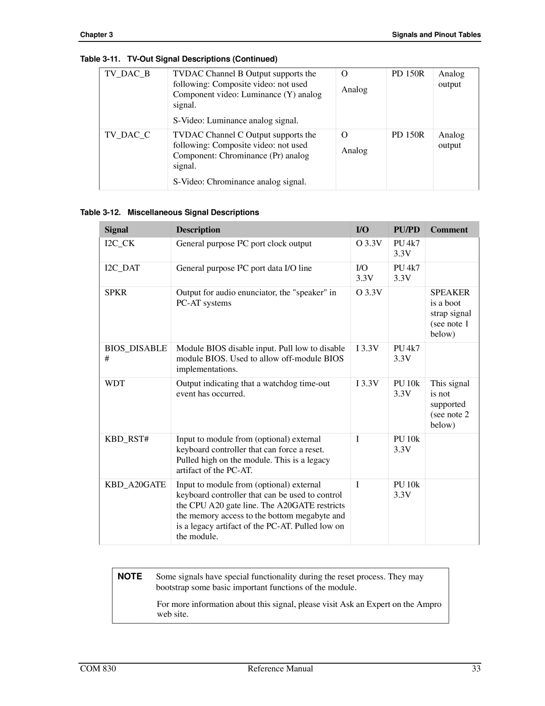
Table |
|
|
|
|
| |||
|
|
|
|
|
|
|
|
|
| TV_DAC_B | TVDAC Channel B Output supports the |
| O | PD 150R |
| Analog | |
|
| following: Composite video: not used |
| Analog |
|
| output | |
|
| Component video: Luminance (Y) analog |
|
|
|
| ||
|
|
|
|
|
|
|
| |
|
| signal. |
|
|
|
|
|
|
|
|
|
|
|
|
|
| |
|
|
|
|
|
|
|
|
|
| TV_DAC_C | TVDAC Channel C Output supports the |
| O | PD 150R |
| Analog | |
|
| following: Composite video: not used |
| Analog |
|
| output | |
|
| Component: Chrominance (Pr) analog |
|
|
|
| ||
|
|
|
|
|
|
|
| |
|
| signal. |
|
|
|
|
|
|
|
|
|
|
|
|
|
| |
|
|
|
|
|
|
|
|
|
Table |
|
|
|
|
| |||
|
|
|
|
|
|
|
|
|
| Signal | Description |
| I/O | PU/PD | Comment | ||
| I2C_CK | General purpose I²C port clock output |
| O 3.3V | PU 4k7 |
|
| |
|
|
|
|
|
| 3.3V |
|
|
| I2C_DAT | General purpose I²C port data I/O line |
| I/O | PU 4k7 |
|
| |
|
|
|
|
| 3.3V | 3.3V |
|
|
| SPKR | Output for audio enunciator, the "speaker" in |
| O 3.3V |
| SPEAKER | ||
|
|
|
|
| is a boot | |||
|
|
|
|
|
|
| strap signal | |
|
|
|
|
|
|
| (see note 1 | |
|
|
|
|
|
|
| below) | |
| BIOS_DISABLE | Module BIOS disable input. Pull low to disable | I 3.3V | PU 4k7 |
|
| ||
| # | module BIOS. Used to allow |
| 3.3V |
|
| ||
|
| implementations. |
|
|
|
|
| |
| WDT | Output indicating that a watchdog |
| I 3.3V | PU 10k | This signal | ||
|
| event has occurred. |
|
| 3.3V | is not | ||
|
|
|
|
|
|
| supported | |
|
|
|
|
|
|
| (see note 2 | |
|
|
|
|
|
|
| below) | |
| KBD_RST# | Input to module from (optional) external |
| I | PU 10k |
|
| |
|
| keyboard controller that can force a reset. |
|
| 3.3V |
|
| |
|
| Pulled high on the module. This is a legacy |
|
|
|
|
| |
|
| artifact of the |
|
|
|
|
| |
| KBD_A20GATE | Input to module from (optional) external |
| I | PU 10k |
|
| |
|
| keyboard controller that can be used to control |
| 3.3V |
|
| ||
|
| the CPU A20 gate line. The A20GATE restricts |
|
|
|
| ||
|
| the memory access to the bottom megabyte and |
|
|
|
| ||
|
| is a legacy artifact of the |
|
|
|
| ||
|
| the module. |
|
|
|
|
| |
|
|
|
|
|
|
|
|
|
NOTE Some signals have special functionality during the reset process. They may bootstrap some basic important functions of the module.
For more information about this signal, please visit Ask an Expert on the Ampro web site.
COM 830 | Reference Manual | 33 |