Chapter 3 | Signals and Pinout Tables |
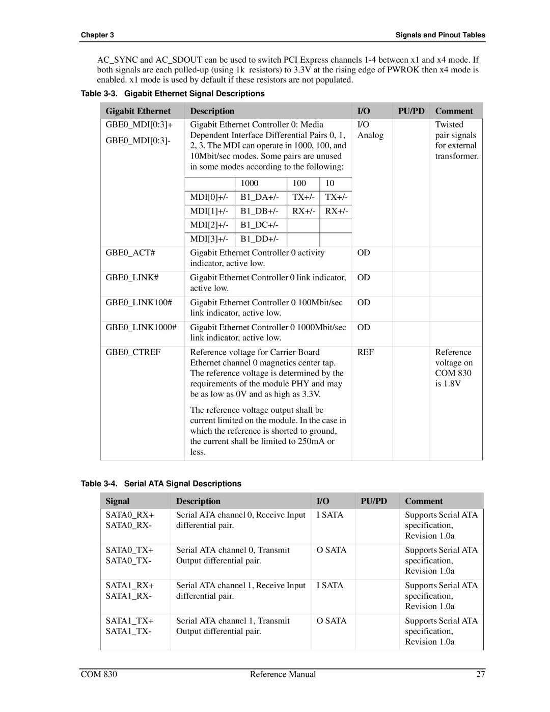
AC_SYNC and AC_SDOUT can be used to switch PCI Express channels
Table
| Gigabit Ethernet |
| Description |
|
|
|
| I/O | PU/PD | Comment | ||||
| GBE0_MDI[0:3]+ |
| Gigabit Ethernet Controller 0: Media | I/O |
|
| Twisted | |||||||
| GBE0_MDI[0:3]- |
| Dependent Interface Differential Pairs 0, 1, | Analog |
|
| pair signals | |||||||
|
| 2, 3. The MDI can operate in 1000, 100, and |
|
|
| for external | ||||||||
|
|
|
|
|
|
| ||||||||
|
|
|
| 10Mbit/sec modes. Some pairs are unused |
|
|
| transformer. | ||||||
|
|
|
| in some modes according to the following: |
|
|
|
| ||||||
|
|
|
|
|
|
|
|
|
|
|
|
|
|
|
|
|
|
|
| 1000 |
| 100 |
|
| 10 |
|
|
|
|
|
|
|
| MDI[0]+/- | B1_DA+/- | TX+/- |
| TX+/- |
|
|
|
| ||
|
|
|
| MDI[1]+/- | B1_DB+/- | RX+/- |
| RX+/- |
|
|
|
| ||
|
|
|
| MDI[2]+/- | B1_DC+/- |
|
|
|
|
|
|
|
|
|
|
|
|
| MDI[3]+/- | B1_DD+/- |
|
|
|
|
|
|
|
|
|
| GBE0_ACT# |
| Gigabit Ethernet Controller 0 activity | OD |
|
|
| |||||||
|
|
|
| indicator, active low. |
|
|
|
|
|
|
|
| ||
| GBE0_LINK# |
| Gigabit Ethernet Controller 0 link indicator, | OD |
|
|
| |||||||
|
|
|
| active low. |
|
|
|
|
|
|
|
| ||
| GBE0_LINK100# |
| Gigabit Ethernet Controller 0 100Mbit/sec | OD |
|
|
| |||||||
|
|
|
| link indicator, active low. |
|
|
|
|
|
|
|
| ||
| GBE0_LINK1000# | Gigabit Ethernet Controller 0 1000Mbit/sec | OD |
|
|
| ||||||||
|
|
|
| link indicator, active low. |
|
|
|
|
|
|
|
| ||
| GBE0_CTREF |
| Reference voltage for Carrier Board | REF |
|
| Reference | |||||||
|
|
|
| Ethernet channel 0 magnetics center tap. |
|
|
| voltage on | ||||||
|
|
|
| The reference voltage is determined by the |
|
|
| COM 830 | ||||||
|
|
|
| requirements of the module PHY and may |
|
|
| is 1.8V | ||||||
|
|
|
| be as low as 0V and as high as 3.3V. |
|
|
|
| ||||||
|
|
|
| The reference voltage output shall be |
|
|
|
| ||||||
|
|
|
| current limited on the module. In the case in |
|
|
|
| ||||||
|
|
|
| which the reference is shorted to ground, |
|
|
|
| ||||||
|
|
|
| the current shall be limited to 250mA or |
|
|
|
| ||||||
|
|
|
| less. |
|
|
|
|
|
|
|
| ||
|
|
|
|
|
|
|
|
|
|
|
|
|
| |
Table |
|
|
|
|
|
|
|
| ||||||
|
|
|
|
|
|
|
|
|
|
|
|
|
|
|
| Signal |
| Description |
|
| I/O | PU/PD |
| Comment | |||||
| SATA0_RX+ |
| Serial ATA channel 0, Receive Input |
| I SATA |
|
| Supports Serial ATA | ||||||
| SATA0_RX- |
| differential pair. |
|
|
|
|
|
| specification, | ||||
|
|
|
|
|
|
|
|
|
|
|
|
| Revision 1.0a | |
| SATA0_TX+ |
| Serial ATA channel 0, Transmit |
|
| O SATA |
|
| Supports Serial ATA | |||||
| SATA0_TX- |
| Output differential pair. |
|
|
|
|
|
| specification, | ||||
|
|
|
|
|
|
|
|
|
|
|
|
| Revision 1.0a | |
| SATA1_RX+ |
| Serial ATA channel 1, Receive Input |
| I SATA |
|
| Supports Serial ATA | ||||||
| SATA1_RX- |
| differential pair. |
|
|
|
|
|
| specification, | ||||
|
|
|
|
|
|
|
|
|
|
|
|
| Revision 1.0a | |
| SATA1_TX+ |
| Serial ATA channel 1, Transmit |
|
| O SATA |
|
| Supports Serial ATA | |||||
| SATA1_TX- |
| Output differential pair. |
|
|
|
|
|
| specification, | ||||
|
|
|
|
|
|
|
|
|
|
|
|
| Revision 1.0a | |
|
|
|
|
|
|
|
|
|
|
|
|
|
|
|
COM 830 | Reference Manual | 27 |