Chapter 3Signals and Pinout Tables
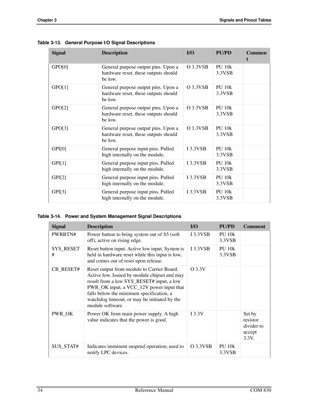
Table
| Signal |
| Description |
| I/O | PU/PD | Commen | ||
|
|
|
|
|
|
|
|
| t |
| GPO[0] |
| General purpose output pins. Upon a |
| O 3.3VSB | PU 10k |
| ||
|
|
| hardware reset, these outputs should |
|
| 3.3VSB |
| ||
|
|
| be low. |
|
|
|
|
|
|
| GPO[1] |
| General purpose output pins. Upon a |
| O 3.3VSB | PU 10k |
| ||
|
|
| hardware reset, these outputs should |
|
| 3.3VSB |
| ||
|
|
| be low. |
|
|
|
|
|
|
| GPO[2] |
| General purpose output pins. Upon a |
| O 3.3VSB | PU 10k |
| ||
|
|
| hardware reset, these outputs should |
|
| 3.3VSB |
| ||
|
|
| be low. |
|
|
|
|
|
|
| GPO[3] |
| General purpose output pins. Upon a |
| O 3.3VSB | PU 10k |
| ||
|
|
| hardware reset, these outputs should |
|
| 3.3VSB |
| ||
|
|
| be low. |
|
|
|
|
|
|
| GPI[0] |
| General purpose input pins. Pulled |
| I 3.3VSB | PU 10k |
| ||
|
|
| high internally on the module. |
|
| 3.3VSB |
| ||
| GPI[1] |
| General purpose input pins. Pulled |
| I 3.3VSB | PU 10k |
| ||
|
|
| high internally on the module. |
|
| 3.3VSB |
| ||
| GPI[2] |
| General purpose input pins. Pulled |
| I 3.3VSB | PU 10k |
| ||
|
|
| high internally on the module. |
|
| 3.3VSB |
| ||
| GPI[3] |
| General purpose input pins. Pulled |
| I 3.3VSB | PU 10k |
| ||
|
|
| high internally on the module. |
|
| 3.3VSB |
| ||
|
|
|
|
|
|
|
|
|
|
Table |
|
|
|
|
| ||||
|
|
|
|
|
|
|
|
|
|
| Signal | Description | I/O |
| PU/PD |
| Comment | ||
| PWRBTN# | Power button to bring system out of S5 (soft | I 3.3VSB |
| PU 10k |
|
| ||
|
| off), active on rising edge. |
|
| 3.3VSB |
|
| ||
| SYS_RESET | Reset button input. Active low input. System is | I 3.3VSB |
| PU 10k |
|
| ||
| # | held in hardware reset while this input is low, |
|
| 3.3VSB |
|
| ||
|
| and comes out of reset upon release. |
|
|
|
|
| ||
| CB_RESET# | Reset output from module to Carrier Board. | O 3.3V |
|
|
|
| ||
|
| Active low. Issued by module chipset and may |
|
|
|
|
| ||
|
| result from a low SYS_RESET# input, a low |
|
|
|
|
| ||
|
| PWR_OK input, a VCC_12V power input that |
|
|
|
|
| ||
|
| falls below the minimum specification, a |
|
|
|
|
| ||
|
| watchdog timeout, or may be initiated by the |
|
|
|
|
| ||
|
| module software. |
|
|
|
|
| ||
| PWR_OK | Power OK from main power supply. A high | I 3.3V |
|
|
| Set by | ||
|
| value indicates that the power is good. |
|
|
|
| resistor | ||
|
|
|
|
|
|
|
|
| divider to |
|
|
|
|
|
|
|
|
| accept |
|
|
|
|
|
|
|
|
| 3.3V. |
| SUS_STAT# | Indicates imminent suspend operation; used to | O 3.3VSB |
| PU 10k |
|
| ||
|
| notify LPC devices. |
|
| 3.3VSB |
|
| ||
|
|
|
|
|
|
|
|
|
|
34 | Reference Manual | COM 830 |