Chapter 3 |
|
|
| Signals and Pinout Tables | ||
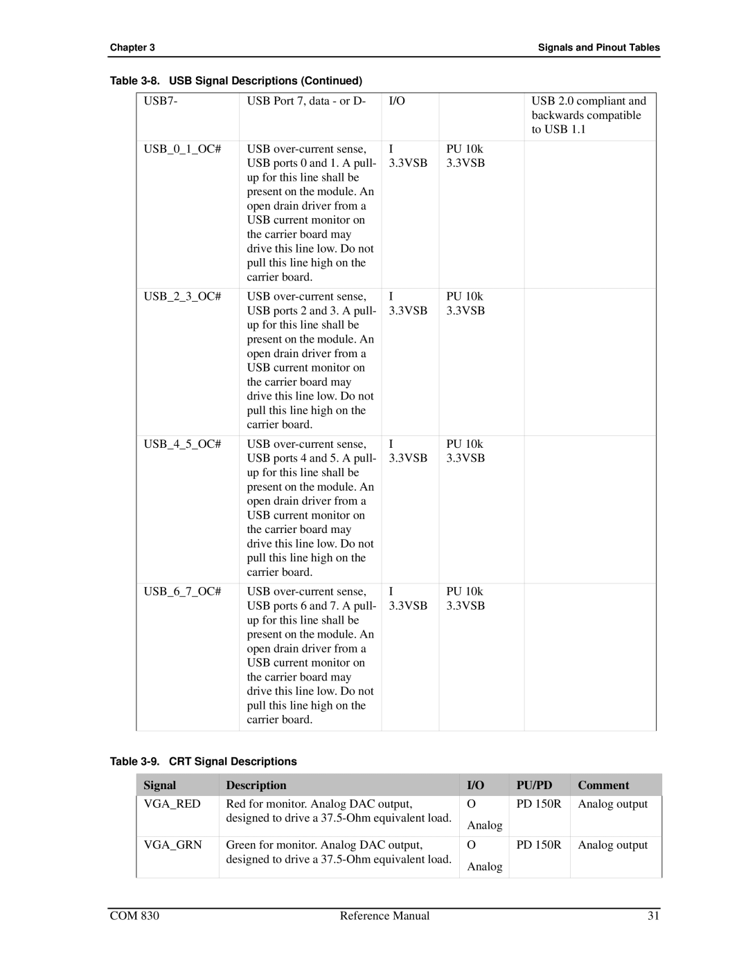
Table |
|
|
|
| ||
|
|
|
|
|
|
|
| USB7- | USB Port 7, data - or D- | I/O |
| USB 2.0 compliant and |
|
|
|
|
|
| backwards compatible |
|
|
|
|
|
| to USB 1.1 |
|
| USB_0_1_OC# | USB | I | PU 10k |
|
|
|
| USB ports 0 and 1. A pull- | 3.3VSB | 3.3VSB |
|
|
|
| up for this line shall be |
|
|
|
|
|
| present on the module. An |
|
|
|
|
|
| open drain driver from a |
|
|
|
|
|
| USB current monitor on |
|
|
|
|
|
| the carrier board may |
|
|
|
|
|
| drive this line low. Do not |
|
|
|
|
|
| pull this line high on the |
|
|
|
|
|
| carrier board. |
|
|
|
|
| USB_2_3_OC# | USB | I | PU 10k |
|
|
|
| USB ports 2 and 3. A pull- | 3.3VSB | 3.3VSB |
|
|
|
| up for this line shall be |
|
|
|
|
|
| present on the module. An |
|
|
|
|
|
| open drain driver from a |
|
|
|
|
|
| USB current monitor on |
|
|
|
|
|
| the carrier board may |
|
|
|
|
|
| drive this line low. Do not |
|
|
|
|
|
| pull this line high on the |
|
|
|
|
|
| carrier board. |
|
|
|
|
| USB_4_5_OC# | USB | I | PU 10k |
|
|
|
| USB ports 4 and 5. A pull- | 3.3VSB | 3.3VSB |
|
|
|
| up for this line shall be |
|
|
|
|
|
| present on the module. An |
|
|
|
|
|
| open drain driver from a |
|
|
|
|
|
| USB current monitor on |
|
|
|
|
|
| the carrier board may |
|
|
|
|
|
| drive this line low. Do not |
|
|
|
|
|
| pull this line high on the |
|
|
|
|
|
| carrier board. |
|
|
|
|
| USB_6_7_OC# | USB | I | PU 10k |
|
|
|
| USB ports 6 and 7. A pull- | 3.3VSB | 3.3VSB |
|
|
|
| up for this line shall be |
|
|
|
|
|
| present on the module. An |
|
|
|
|
|
| open drain driver from a |
|
|
|
|
|
| USB current monitor on |
|
|
|
|
|
| the carrier board may |
|
|
|
|
|
| drive this line low. Do not |
|
|
|
|
|
| pull this line high on the |
|
|
|
|
|
| carrier board. |
|
|
|
|
|
|
|
|
|
|
|
Table
Signal | Description | I/O | PU/PD | Comment |
VGA_RED | Red for monitor. Analog DAC output, | O | PD 150R | Analog output |
| designed to drive a | Analog |
|
|
|
|
|
| |
|
|
|
|
|
VGA_GRN | Green for monitor. Analog DAC output, | O | PD 150R | Analog output |
| designed to drive a | Analog |
|
|
|
|
|
| |
|
|
|
|
|
COM 830 | Reference Manual | 31 |