Chapter 3 |
|
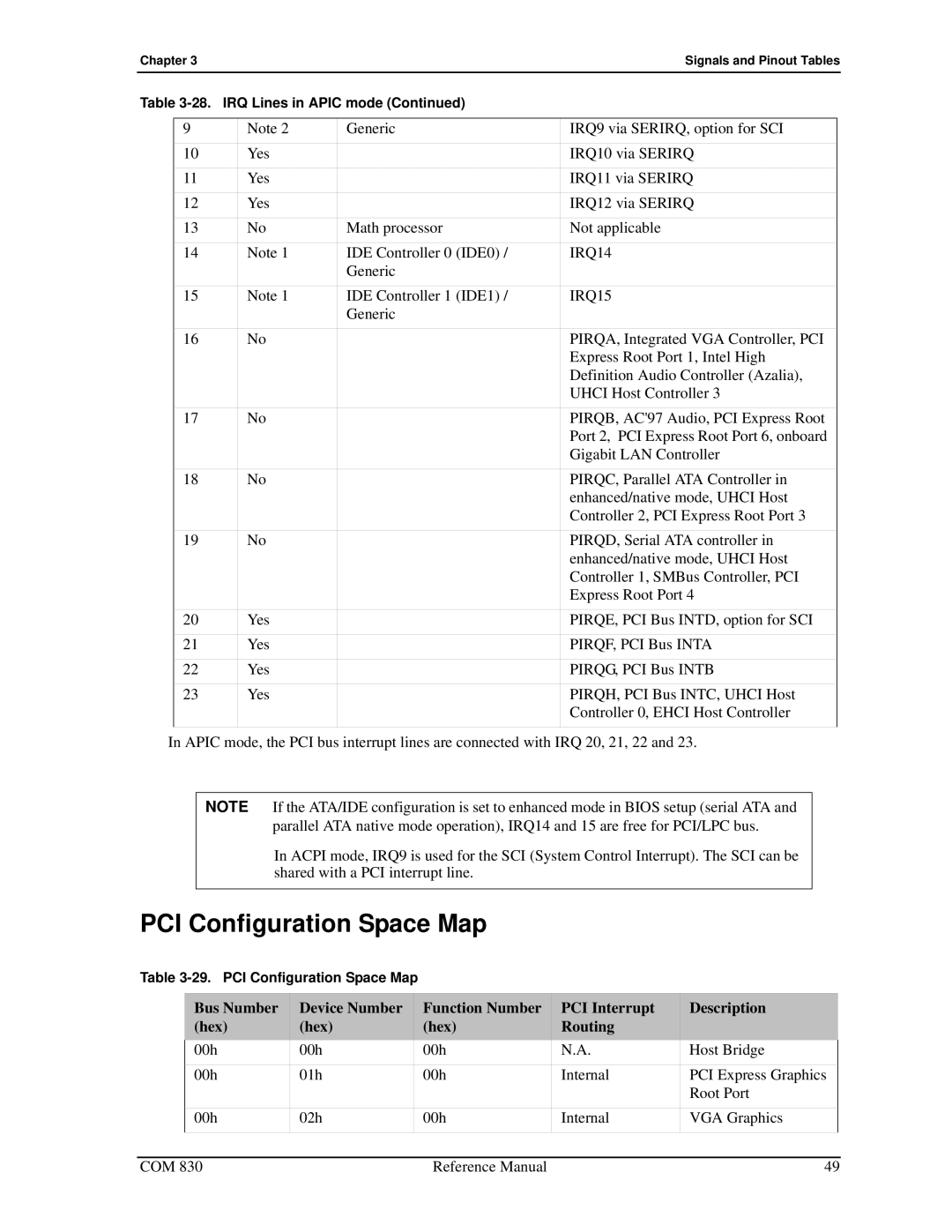
| Signals and Pinout Tables | ||
Table |
|
| |||
|
|
|
|
|
|
| 9 | Note 2 | Generic | IRQ9 via SERIRQ, option for SCI |
|
| 10 | Yes |
| IRQ10 via SERIRQ |
|
| 11 | Yes |
| IRQ11 via SERIRQ |
|
| 12 | Yes |
| IRQ12 via SERIRQ |
|
| 13 | No | Math processor | Not applicable |
|
| 14 | Note 1 | IDE Controller 0 (IDE0) / | IRQ14 |
|
|
|
| Generic |
|
|
| 15 | Note 1 | IDE Controller 1 (IDE1) / | IRQ15 |
|
|
|
| Generic |
|
|
| 16 | No |
| PIRQA, Integrated VGA Controller, PCI |
|
|
|
|
| Express Root Port 1, Intel High |
|
|
|
|
| Definition Audio Controller (Azalia), |
|
|
|
|
| UHCI Host Controller 3 |
|
| 17 | No |
| PIRQB, AC'97 Audio, PCI Express Root |
|
|
|
|
| Port 2, PCI Express Root Port 6, onboard |
|
|
|
|
| Gigabit LAN Controller |
|
| 18 | No |
| PIRQC, Parallel ATA Controller in |
|
|
|
|
| enhanced/native mode, UHCI Host |
|
|
|
|
| Controller 2, PCI Express Root Port 3 |
|
| 19 | No |
| PIRQD, Serial ATA controller in |
|
|
|
|
| enhanced/native mode, UHCI Host |
|
|
|
|
| Controller 1, SMBus Controller, PCI |
|
|
|
|
| Express Root Port 4 |
|
| 20 | Yes |
| PIRQE, PCI Bus INTD, option for SCI |
|
| 21 | Yes |
| PIRQF, PCI Bus INTA |
|
| 22 | Yes |
| PIRQG, PCI Bus INTB |
|
| 23 | Yes |
| PIRQH, PCI Bus INTC, UHCI Host |
|
|
|
|
| Controller 0, EHCI Host Controller |
|
|
|
|
|
|
|
In APIC mode, the PCI bus interrupt lines are connected with IRQ 20, 21, 22 and 23.
NOTE If the ATA/IDE configuration is set to enhanced mode in BIOS setup (serial ATA and parallel ATA native mode operation), IRQ14 and 15 are free for PCI/LPC bus.
In ACPI mode, IRQ9 is used for the SCI (System Control Interrupt). The SCI can be shared with a PCI interrupt line.
PCI Configuration Space Map
Table
Bus Number | Device Number | Function Number | PCI Interrupt | Description |
(hex) | (hex) | (hex) | Routing |
|
00h | 00h | 00h | N.A. | Host Bridge |
00h | 01h | 00h | Internal | PCI Express Graphics |
|
|
|
| Root Port |
00h | 02h | 00h | Internal | VGA Graphics |
|
|
|
|
|
COM 830 | Reference Manual | 49 |