User’s Manual
IntraSwitch Series
Limited Lifetime Warranty
Table of Contents
LED Indicators
Installation
Setting Up For Management
Status Monitoring and Statistics
Console Management
Web Browser Management
Advanced Management
Vlan Management
Index-1
Index
List of Figures
IntraSwitch 6216M Front Panel
Statistics Menu
List of Tables
Page
About This Manual
Chapter Contents Document Conventions Audience
About This Manual
Manual Contents
Document Conventions
Document Conventions
About This Manual
Introduction
IntraSwitch 6216M
IntraSwitch 6216M
IntraSwitch
IntraSwitch
IntraSwitch Components
Configuration/ Management
Switching Capacity
Console/Telnet Management
Web Browser Management
Intelligent Forwarding Chassis Design
Package Contents
Tools and Materials Required
Tools Materials
Configuration Default Setting
Factory Defaults
Factory Defaults
Installation
Installation Guidelines
Installing the IntraSwitch
Installation Overview
Equipment Rack Installation
Rack Mounting Desktop Placement
Free-Standing Desktop Installation
Modules IntraSwitch 6216M Only
Installing Asanté MII
Connecting to the Network
Connecting Power
10/100 Ports Cabling Procedures
10Base-FL Module
MII Expansion Ports Cabling Procedures
10/100 Ports Cable Guidelines
100Base-FX MII Module Cable Guidelines
Configuring for Management
BootP Configuration
Console Configuration
Using a straight-throughRS-232 cable with a
Configuring for Management
Installation
LED Indicators Port LEDs Function Indicator Lights
LED Indicators
IntraSwitch 6216M and 6224 LED Indicators
LED Indicators
IntraSwitch 6216M and 6224, Common LEDs
IntraSwitch 6216M LEDs
IntraSwitch 6224 LEDs
IntraSwitch 6216M and 6224 Port LEDs
IntraSwitch 6216M and 6224Port LED Descriptions
100Mbps Green Port speed is 100Mbps
IntraSwitch 6216M Indicator Light Description
IntraSwitch 6216M Function LEDs
IntraSwitch 6224 Indicator Light Descriptions
Setting Up For Management
Management Options
IntraSwitch Management
In-Band Management
Out-of-Band Management
Local Management Interface Main Menu
In-Band Management
Setting Up For Management SNMP-Based Management Software
Console Management
Configuration Tasks
Console Management
Management Tasks
Management Tasks
Local Management Interface
Accessing a Submenu Exiting a
Main Menu
General Information Menu
Accessing the General Information Menu
Logging into the Configuration Menu
Configuration Menu
Configuration Menu Options
Configuration Menu Options
Change Password
System Reset Options
Menu Item Description Tftp Image File
Downloading Configuration
Current Settings
System Administration Configuration
System Administration Configuration Menu Settings
System IP Configuration
Changing System Administration Information
System IP Configuration Menu
System IP Configuration Menu Settings
Changing System IP Information
Bootstrap Configuration
Image Banks
BootStrap Configuration Menu
Bootstrap Configuration Menu Settings
Setting Description Load Mode
Selecting the Boot Bank Number
Boot Bank
Loading Software Locally
Loading Software Remotely
Select option Set Boot Server IP Address
Snmp Configuration Menu
Snmp Configuration
Changing Community Strings
Snmp Configuration Menu Settings
Adding a Trap Receiver
Enabling Authentication Traps
Type a to Add a Trap Receiver
Deleting a Trap Receiver
Port Configuration
Type d to Delete a Trap Receiver
Port Configuration
Current Port Settings
IntraSwitch System Information
Port Management Menu Settings
Enabling or Disabling a Port
Setting Description Port Status
Auto-Neg
Link Status
Configuring Duplex Mode
Setting Broadcast BC Filtering
Configuring an IntraSwitch’s Port for Auto-negotiation
Configuring Auto-negotiation
Modifying Auto-negotiation Advertisement
Forwarding Database/Security Configuration
Spanning Tree Configuration
10 Forwarding DB/Security Configuration Menu
Displaying the MAC Address Table
Security Configuration Menu Settings
Open the Forwarding DB/Security Con
Searching the MAC Address Table
Number next to Enter Port Number
Setting the MAC Address Age-Out Time
Enabling the Duplicated-IP Trap
Enabled
Viewing the Trap Log
Image Downloading Through Tftp
Image File Downloading Configuration
13 Image Downloading Menu
Type s to set the Image Server Address
Performing a Software Upgrade at Runtime
Return
Serial Downloading Configuration
Type d to Download the Image toFile
11 X/Y/Z Downloading Menu Table
Setting Description Download Protocol
Current Baud Rate
Version Date
Performing Software Upgrade
System Reset Options
12 Reset Menu Settings
16 Reset Menu
Scheduling a Reset
Resetting the IntraSwitch
Viewing the System Log
System Log
18 System Log Display
Clearing the System Log
Set Menu Idle Time-out
13 UI Time-out Settings
Press ctrl-c
To set the Console Idle Time-out Period
To set the Telnet Idle Time-out period
Changing the Password
Setting Description Port Operating Status
14 Global Port Configuration Settings
Global Port Configuration
Port Auto-negotiation
23 Global Port Configuration Help Menu
Global Configuration Operations
Option h, prompt for confirmation. Press y
24 Auto-negotiation Advertisement Summary Screen
Status Monitoring Statistics
Viewing Current Operating Information
Monitoring the IntraSwitch
General Information Menu Parameters
Viewing Current Operating Information
Viewing IntraSwitch System Information
Viewing Statistics
IntraSwitch System Information
Statistics Fields on Statistics Screen
Statistics Menu
Statistics Since Last Reset
Statistics Since Last Reset
Counters Screen Description
Following table describes the Counters screen
Viewing Statistics
Status Monitoring and Statistics
Advanced Management
Spanning Tree Protocol
Advanced Management
How it Works
Enabling/ Disabling STP
Configuring STP Parameters
Spanning Tree Configuration Menu Settings
Configuring Switch Priority
Configuring Timers
Type a in the Spanning Tree Configuration
Open the Spanning Tree Configuration
Setting Storm Detection Threshold
Setting Storm Duration
Configuring STP Port Parameters
Root Port
Spanning Tree Port Configuration Menu Settings
Advanced Management
Download Image Tech Support
Web Browser Management
Web Browser Management
Accessing with a Web Browser
Overview
Management buttons
Page
Port Selector Screen
Port Selector Feature
General Information Screen
General Info Screen
Web Browser Management
Statistics Screen
Statistics Screen
Web Browser Management
Statistics Counters Screen
Statistics Counters Screen
Port Configuration Screen
Port Configuration Screen
Spanning Tree Protocol Configuration
Spanning Tree Screen
STP Port Configuration
STP Port Configuration Screen
Snmp Configuration Screen
Snmp Configuration Screen
Download Image File
Downloading Image File Screen
Asanté Technical Support Screen
11 Asanté Technical Support Screen
Vlan Port Attribute Configuration
Overview Vlan Configuration
Snmp Management
Vlan Management
Vlan Groups
Abbreviations
Vlan Untagged normal Ports
Vlan Tagged Expansion Ports
Spanning Tree Protocol in Vlan environment
Management VLANs
Vlan Configuration
System Vlan Default Settings
Vlan Management Interface Options
No Ports 0012 Enabled 0013 0014 No ports 0015
Accessing Configuration Menus
Vlan Configuration Screen
Current Settings
Default VLAN, which by default is equal to
Vlan Group Current Settings
This field represents the current VID
Vlan Group. The user can set this value
Setting Vlan Name Adding Vlan Members
Type 0 to make management belong to all
Vlan Port Attribute Configuration Screen
Vlan Port Attribute Configuration
Current Settings of Port Attributes
Setting the Port
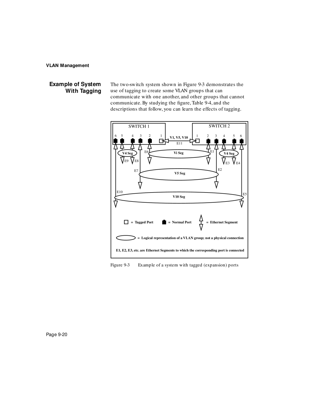
Overview Using tagging to connect VLANs
Toggle Vlan Tagging
Important! The Vlid numbers for
Map a Port to Multi- ple Vlan Groups
Removing VLANs from a Tagged Port
Return to Port Attributes Configu- ration Menu
Example of System With Tagging
Switch
Status of Ethernet Segments in Example
Disabled SW1 and SW2 not connected
Configuration used in example of tagging
Snmp Management
Power LED Error Type/Cause Solution Options or Steps
Troubleshooting
A-2
Technical Specifications
Power Specifications
Weight
Environmental Specifications
Standards Compliance
Technical Support
Technical Support
Index
Numerics
Index
Dram
Viewing
MAC
Remote 4-3
Package contents 1-7packets, broadcast 5-22parameters, Snmp
Software 5-15
Index
Configuring 5-9, 5-11, 5-14, 5-17, 5-28
Management 9-6, 9-7
Index
Index
Index
Index
Index
Index
Index
Index
Index
Index
Index
Index