Axis A1001 Network Door Controller & Axis Entry Manager
Trademark Acknowledgments
About this Document
Liability
Intellectual Property Rights Equipment Modifications
Learn More
Support
Axis A1001 Network Door Controller & Axis Entry Manager
Front and back
Hardware Overview
Interface
External power inputs
Power outputs
Color Indication
LED Indicators
LED indicators, buttons and other hardware
Power Connector
Connectors and Buttons
External Power Inputs
For technical specifications, see
Buttons and Other Hardware
Power Outputs
Start a browser Chrome, Internet Explorer, Firefox, Safari
Access from a Browser
Access from the Internet
Set the Root Password
Overview
Select a Language
Configuration Step by Step
To import a hardware configuration file
Configure the Hardware
Import a Hardware Configuration File
Export a Hardware Configuration File
Motorized locks must be configured as secondary locks
Create a New Hardware Configuration
Configure Locks and Door Monitors
To create a new hardware configuration from the beginning
Lock Options
Following reader options are available
Configure Readers and REX Devices
Use Supervised Inputs
Reader and REX Device Options
Verification Controls
Verify the Hardware Connections
Set the Date and Time
Get the Date and Time from the Computer
Configure the Network Settings
Set the Date and Time Manually
Go to Setup Configure Card Formats
Configure Card Formats
Basic TCP/IP Settings
To enable card formats
Field Maps
Card Format Descriptions
Connected Door Controllers List
Manage Network Door Controllers
Door Controller System Status
Connected Door Controllers in the System
Remove Door Controllers from the System
Click Reset hardware configuration
IP address MAC address
Maintenance Instructions
Choose a Workflow
Access Management
About Users
Access Schedule Types
Create and Edit Access Schedules
Add Schedule Items
Group Credentials
Go to Access Management Groups tab, click Add new group
Create and Edit Groups
Manage Doors
Click Add scheduled unlock
Identification Types
Add Scheduled Unlock States
Manual Door Actions
Go to Access Management
Create and Edit Users
Use Manual Door Actions
First name required Last name
User Credentials
Import Users
Following credentials are available for users
Export Users
Example Access Schedule Combinations
Create a Subtraction schedule called Nights & weekends
Event Log Filters
View the Alarm Log
Configure the Event and Alarm Logs
View the Event Log
Event Log Options
Set Up Action Rules
Alarm Log Options
Go to Events Action Rules and click Add
Access Point
Configuration
Triggers
Hardware
Door
Add Recipients
Actions
Following recipients are available
Set Up Email Recipients
Create Schedules
Recipient Types
Beeper pattern State Dual LED Single LED
Set Up Recurrences
Reader Feedback
Event Wiegand
Click Print selected columns
View, Print, and Export Reports
Report Types
Click View and print
IP Address Filter
To enable Https on the Axis product
Security
Users
Certificates
To allow the product to access a network protected by Ieee
Ieee
Create a self-signed certificate as described above
Click Install certificate and upload the certificate
Date & Time
Network
Linux/Unix example
Assign IP Address Using ARP/Ping
ARP/Ping
Linux/Unix syntax
NTP Configuration
Advanced TCP/IP Settings
Axis Internet Dynamic DNS Service
DNS Configuration
Link-Local IPv4 Address
Host Name Configuration
Information, see the online help
QoS Quality of Service
Ports & Devices
Maintenance
Logs & Reports
Support
Support Overview
System Overview
File Upload
Reset to Factory Default Settings
Advanced
Scripting
UNIX/Linux, type the following from the command line
Upgrade the Firmware
Emergency Recovery Procedure
Firmware To upgrade the product’s firmware
Product is accessible locally but not externally
Symptoms, Possible Causes and Remedial Actions
Problems setting the IP address
Product cannot be accessed from a browser
Hardware failure
Status and Network indicator LEDs are flashing red rapidly
Axis A1001 Network Door Controller
Weight
Function/group Specifications General Casing
Power
Connectors
Axis Entry Manager
Connectors
Function Pin
Reader Data Connector
Reader I/O Connector
Function Pin Specifications
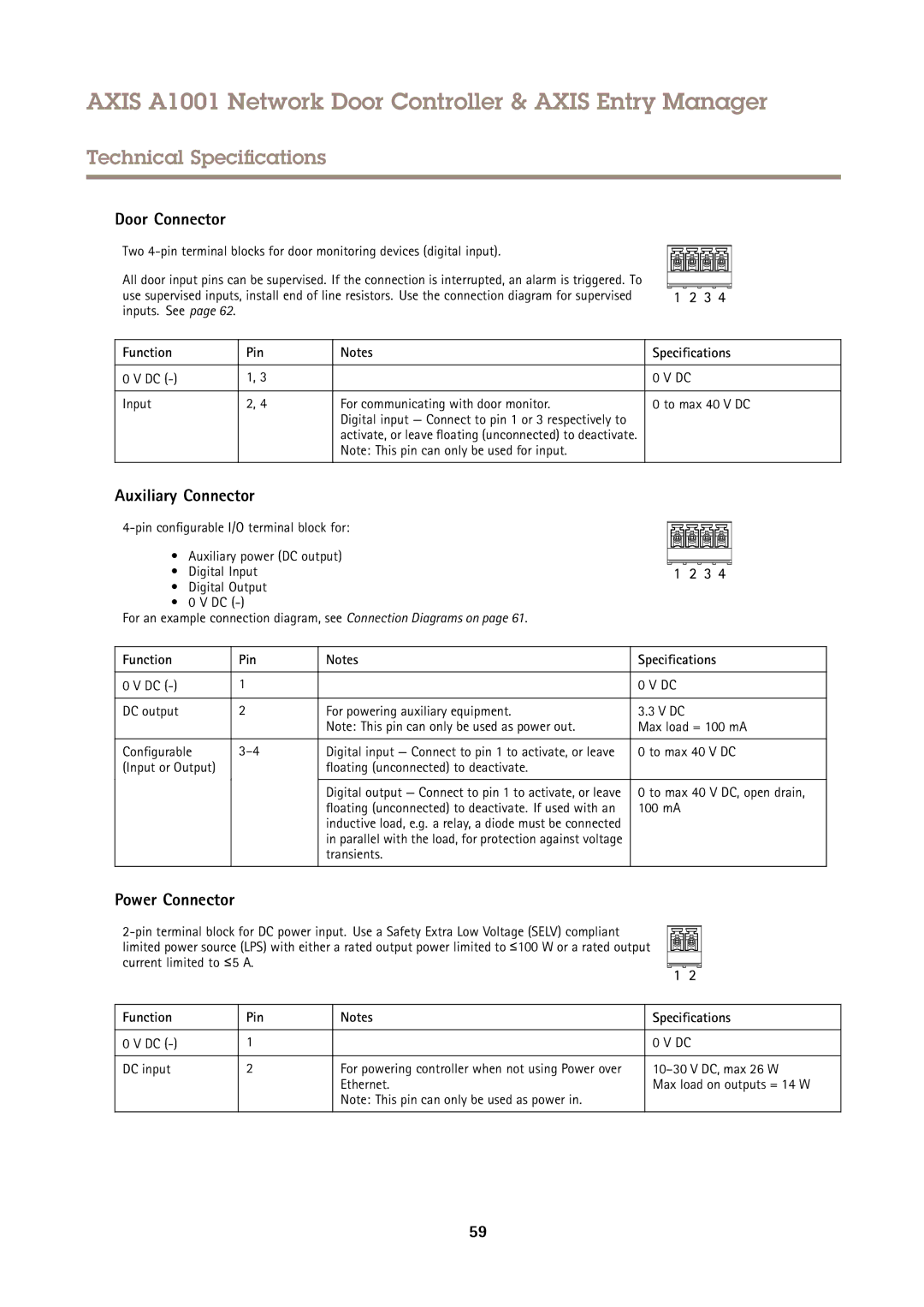
Power Connector
Door Connector
Auxiliary Connector
Tampering Alarm Pin Header
Network Connector
Power Lock Connector
Power & Relay Connector
Back tampering alarm
Connection Diagrams
Supervised Inputs
M5.7