BayTech Manual Publication #U140A124-01 August
DS-RPC Data SWITCH/POWER Control
Page
Iii
Page
Introduction to the DS-RPC
DS71-MD2
Technical Support
Page
Introduction to the DS-RPC
Page
DS71 or DS71-MD2 Host Module
Programmable Features of the DS Modules
Feature Description Action
Feature Description Action DS71-MD2 Host Module
Programmable Features of the DS Modules con’t
Module
Feature Description Action DS73TP N Etwork
Operation
DS-RPC Quick Start
EIA-232 Serial Connection
Selecting a Device
DS-RPC Module Configuration
RPC
Unpacking
Installation
Power
Preparing the Installation Site
Circuit Breaker
Power ON/OFF State
Power UP Sequence
DS73TP Connection
Cabling
RJ-45 Cables and Adapters
DS71 EIA-232 RJ-45 Pin/Signal Definition
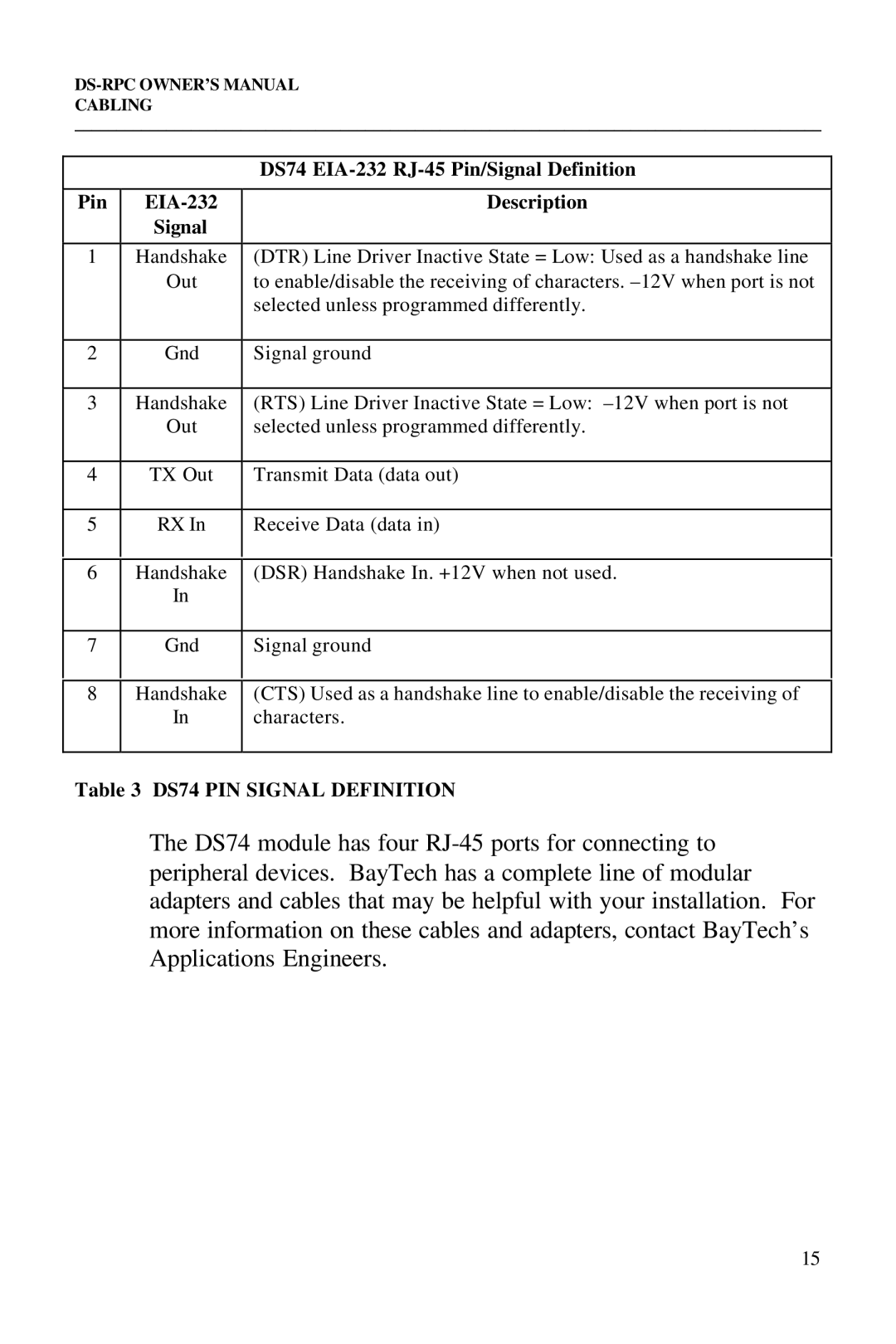
DS74 EIA-232 RJ-45 Pin/Signal Definition
Modem Connections
PIN
Connection
Detailed Operation Configuration
Connecting to the DS-RPC
EIA-232 Serial
DS71-MD2 only
Detailed Operation and Configuration
Operation
Device a Device B Device C Device D
String
Menu Driven
Selection
Ascii Character
Mode
Binary Mode
$BT2,1cr$BTBcr
Terminate Binary
Menu
PPP DIAL-UP
Configuration
Status
Or this for the DS71-MD2
Serial Port
Configuration
DTR RTS
115.2K None Off High Exit/Save..….......1
Selecting #1 will give the same results as
Cr. New configuration changes are stored
If you have made necessary changes to
Host device, type Y for yes, followed by
For For 57.6K a for 76.8K B for 115.2K Enter Request
For
DTR RTS Host
Code is $BT
User programmable. Default Port Select
Port Select
Code
Character
Guard is disabled
ID Echo
Default Connect Port ID Echo is disabled
Connect Port
Header
Login Setup
Header is enabled
Default Password is BTA, disabled.
Password
Menu
Auto Connect Port
If enabled, the following header and menu appears
Serial connection
Port is disabled
Escape Character ........…
Rings to Answer is
Disabled
Rings to
Answer
Minutes
Timeout
Default Connectivity Timeout is
Connectivity
2B Hex or a plus sign +
Default Escape Character is 43, which is
Escape
Character
Or DS71-MD2
Identifies the unit. Default Unit ID is DS71
Unit Reset
Unit ID
Ascii
Driven
Port Device Name …..............................3
Selections 1-8 are fully programmable
DS73TP
Enter password
Dial-UP
Subnet Mask
Default Dial-Up IP Address is
Default Subnet Mask is
DNS
Default Gateway address is
Gateway
Primary
0.0
Default Primary DNS address is
Menu. Default Secondary DNS address is
Secondary
Nbns
Default Primary Nbns address is
Default Secondary Nbns address is
User Name
Default User Name is user1
Default Password is BTA
Name
Default Module Name is DS73TP
Module
RPC Operation
Accessing Main Menu
Controlling Receptacles
Outlet 1, Outlet 2, Outlet 3, Outlet
DS-RPC Config
Change Password
Outlet Outlet 4 Enter Request
Confirmation
Enable/Disable
Is Enabled
RPC
Technical Support
OUTLET3 Outlet
DS-RPC Model DS-RPC Serial Number
Module
Outlet
REPACKAGING, Shipping and Returning to the Factory
Call BayTech to get a Return Authorization Number
FCC Requirements for the DS71-MD2
FCC Radio Frequency Interface Statement
FCC Radio Frequency Interface Statement
Table A.1
Specifications
Appendix a
Base DS71 Host DS71-MD2 DS74
Appendix B
Save modem’s configuration in non-volatile memory
Rockwell Chip SET Modems Command Interpretation
Make NEW Connection
Appendix C
MY Computer
DIAL-UP Networking
Properties
Post Dial Terminal Screen
DS71 Mechanical Layout
Appendix D Drawings
DS71-MD2 Mechanical Layout
DS74 Mechanical Layout
DS73 Mechanical Layout
Ascii Character Definition
Appendix E
Break condition ·
Rings to Answer · 45, 46 RTS/DTR Line Driver · 29, 31
XON/XOFF ·