High Speed Pan/Tilt SystemInstalling the High Speed Pan/Tilt en 11
4 | Installing the High Speed Pan/Tilt | |
| This chapter outlines the procedures needed to install the High Speed Pan/Tilt. Installation | |
| should only be done by qualified service personnel in conformance to all local codes. | |
|
|
|
| i | NOTICE! |
| The High Speed Pan/Tilt unit cannot be mounted upside down! This will stress | |
| bearings and mechanical components; no liabilities are accepted and all | |
| warranties are void. | |
|
| |
|
|
|
4.1 | Mounting the High Speed Pan/Tilt |
The High Speed Pan/Tilt System can be mounted with either a wall mount
To install the device, proceed as follows:
1.Determine the location to install the device.
–When selecting a location, a minimum clearance of 300 mm (12 in.) in front of the unit and 300 mm (12 in.) in back of the unit is required to facilitate component removal and installation.
–The device should be installed vertically. Any other position could impair the perfor- mance of the device.
–Do not attach the device upside down.
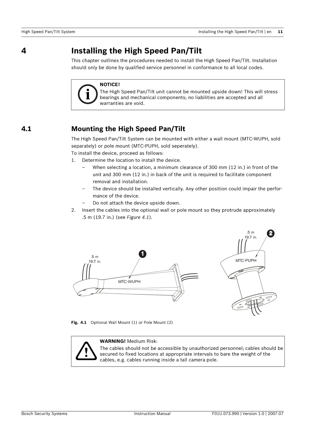
2.Insert the cables into the optional wall or pole mount so they protrude approximately
.5 m (19.7 in.) (see Figure 4.1).
.5 m2
19.7 in.
.5 m | 1 | |
19.7 in. |
Fig. 4.1 Optional Wall Mount (1) or Pole Mount (2)
WARNING! Medium Risk:
!The cables should not be accessible by unauthorized personnel; cables should be secured to fixed locations at appropriate intervals to bare the weight of the cables, e.g. cables running inside a tall camera pole.
Bosch Security Systems | Instruction Manual | F01U.073.990 Version 1.0 2007.07 |
