Chapter 2 Getting Started
Installing the IP Camera
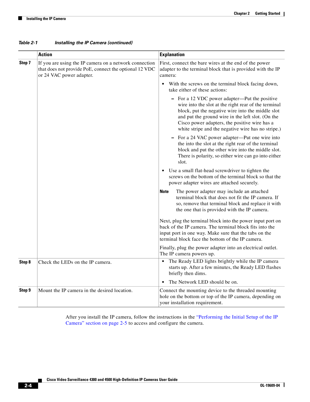
Table | Installing the IP Camera (continued) |
|
|
|
|
| Action | Explanation |
|
|
|
Step 7 | If you are using the IP camera on a network connection | First, connect the bare wires at the end of the power |
| that does not provide PoE, connect the optional 12 VDC | adapter to the terminal block that is provided with the IP |
| or 24 VAC power adapter. | camera: |
|
| • With the screws on the terminal block facing down, |
|
| take either of these actions: |
|
| – For a 12 VDC power |
|
| wire into the slot at the right rear of the terminal |
|
| block, put the negative wire into the middle slot |
|
| and put the ground wire in the left slot. (On the |
|
| Cisco power adapters, the positive wire has a |
|
| white stripe and the negative wire has no stripe.) |
|
| – For a 24 VAC power |
|
| the into the slot at the right rear of the terminal |
|
| block and put the other wire into the middle slot. |
|
| There is polarity, so either wire can go into either |
|
| slot. |
|
| • Use a small |
|
| screws on the bottom of the terminal block so that the |
|
| power adapter wires are attached securely. |
|
| Note The power adapter may include an attached |
|
| terminal block that does not fit the IP camera. If |
|
| so, remove that terminal block and replace it with |
|
| the one that is provided with the IP camera. |
|
| Next, plug the terminal block into the power input port on |
|
| back of the IP camera. The terminal block fits into the |
|
| input port in one way. Make sure that the tabs on the |
|
| terminal block face the bottom of the IP camera. |
|
| Finally, plug the power adapter into an electrical outlet. |
|
| The IP camera powers up. |
|
|
|
Step 8 | Check the LEDs on the IP camera. | • The Ready LED lights brightly while the IP camera |
|
| starts up. After a few minutes, the Ready LED flashes |
|
| briefly then dims. |
|
| • The Network LED should be on. |
|
|
|
Step 9 | Mount the IP camera in the desired location. | Connect the mounting device to the threaded mounting |
|
| hole on the bottom or top of the IP camera, depending on |
|
| your installation requirement. |
|
|
|
After you install the IP camera, follow the instructions in the “Performing the Initial Setup of the IP Camera” section on page
Cisco Video Surveillance 4300 and 4500
| ||
|