Chapter 1 Overview
|
|
|
|
| IP Camera Physical Details |
|
|
|
| ||||
4 | LAN port | Accepts a standard LAN cable to connect the IP camera to a | ||||
|
| 100BaseT hub, router, or switch. | ||||
|
|
| ||||
5 | Network Activity LED | Indicates information about the network connections as follows: | ||||
|
|
| • Lit | |||
|
|
| • | |||
|
|
| • | |||
|
|
| connection | |||
|
|
| ||||
6 | Power input | Provides for the connection of an optional 12 V, 1 amp DC power | ||||
|
| adapter or 24 VAC power adapter. | ||||
|
|
|
|
|
|
|
|
| Caution Use only the Cisco specified power supply adapter. | ||||
|
|
|
|
| ||
|
|
| ||||
7 | Reset button | Recessed button that reboots the IP camera or resets it to a default | ||||
|
| state. You can use a pin or paper clip to depress it. It can be used | ||||
|
| any time that the IP camera is on and can have various effects, as | ||||
|
| described in the “Resetting the IP Camera” section on page | ||||
|
|
| ||||
8 | GPIO ports | General purpose input/output (GPIO) terminal block that includes | ||||
|
| 2 input ports (labeled DI1, DI2), 2 output ports (labeled DO1, | ||||
|
| DO2), a grounding port (labeled GND), and a a | ||||
|
|
| ||||
9 | USB port | Not supported. | ||||
|
|
|
|
|
|
|
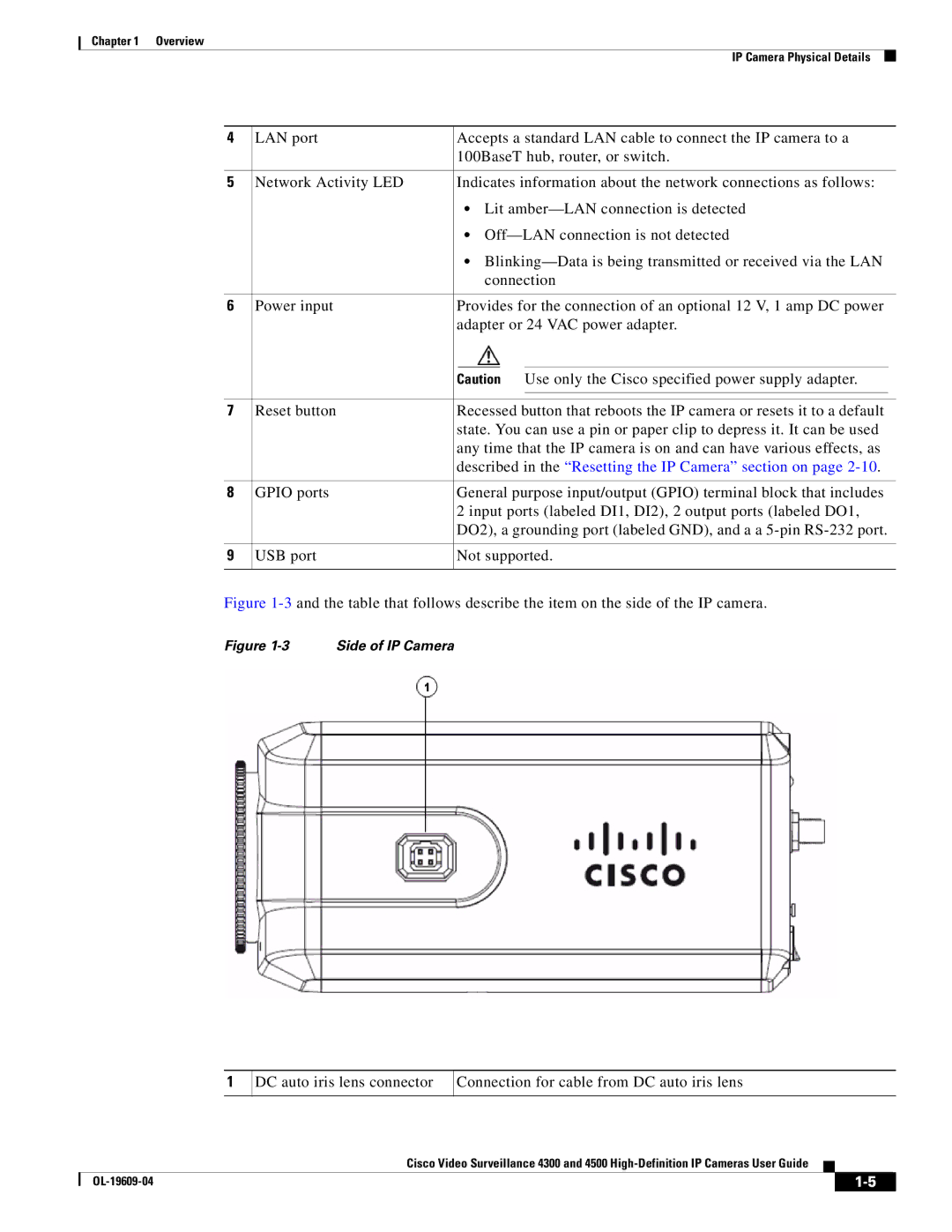
Figure 1-3 and the table that follows describe the item on the side of the IP camera.
Figure 1-3 Side of IP Camera
1
DC auto iris lens connector
Connection for cable from DC auto iris lens
Cisco Video Surveillance 4300 and 4500
|
| ||
|
|