Chapter 3 Configuring and Managing the IP Camera

Feature Setup Windows

Event state—Indicates whether the event is active or inactive at the time that the event was detected for this notification

Event description—Description of the event.

Input port ID—If the event was triggered by an input port state change, port ID of the port

Region index—If the event was triggered by motion detection, identification number of the region in which the IP camera detected motion

Sensitivity level—If the event was triggered by motion detection, sensitivity that is configured for the region in which motion was detected

Detection threshold—If the event was triggered by motion detection, threshold that is configured for the region in which motion was detected

Email notification—An event can cause the IP camera to send a notification e-mail message to designated recipients. The message can include a video file or still image of the activity that triggered the event.

This message includes the same information that is provided with HTTP notification.

Output port state change—Changes the state of an IP camera output port from low to high or from high to low.

Syslog server message—Sends a notification message to the designated Syslog server.

The Event Notification window also allows you to designate schedules. If an event takes place within a designated schedule, the IP camera takes the actions that you configure.

To display the Event Notification window, access the configuration windows as described in the “Performing the Initial Setup of the IP Camera” section on page 2-5, click Feature Setup, then click Event.

If you change any options in this window, you must click the Save Settings button to save the change. If you do not click this button, changes are not retained when you exit the window. Save Settings appears at the bottom of the window. You may need to scroll down to it.

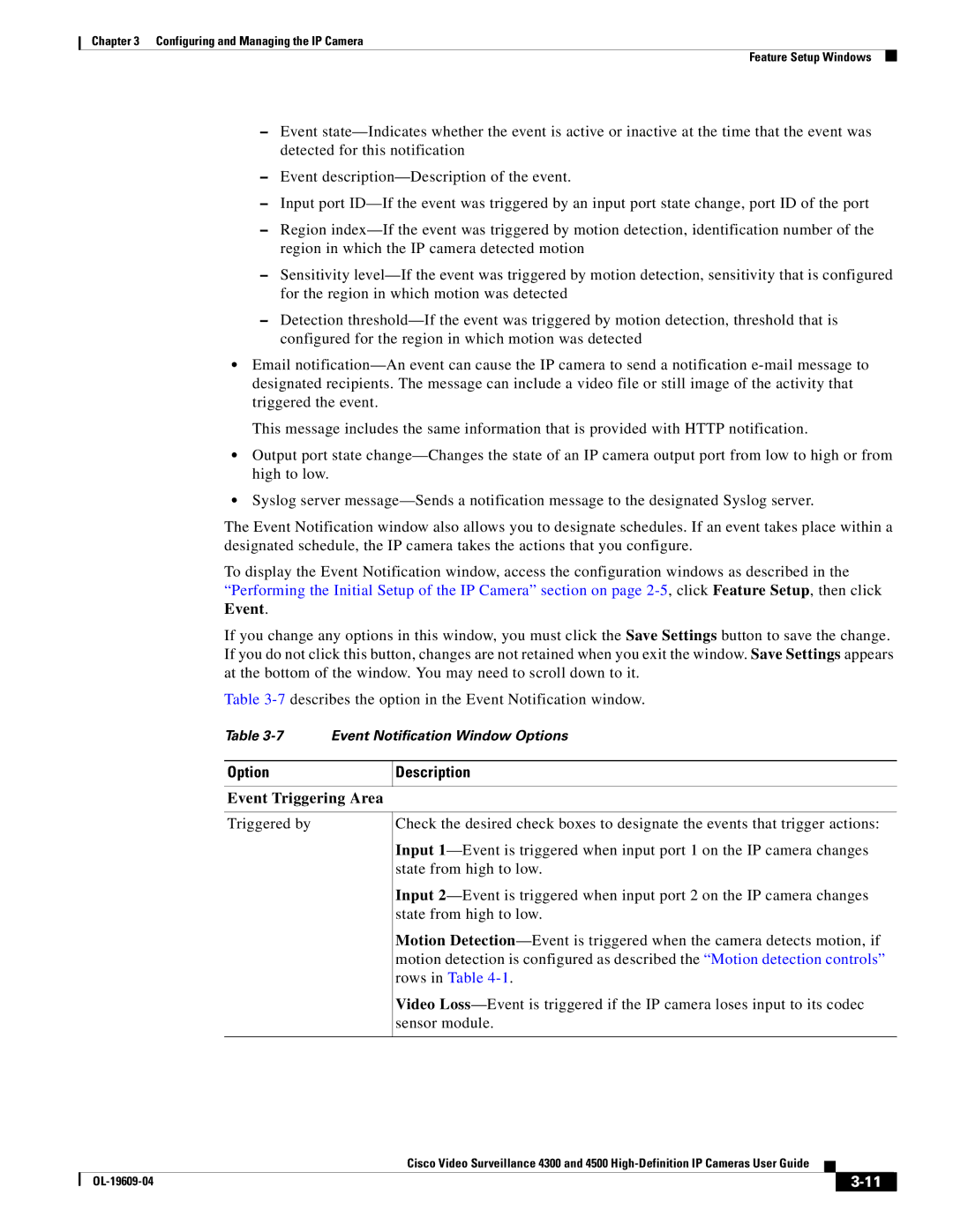
Table 3-7describes the option in the Event Notification window.

Table 3-7 Event Notification Window Options

Option

Description


Event Triggering Area

Triggered by

Check the desired check boxes to designate the events that trigger actions:

Input 1—Event is triggered when input port 1 on the IP camera changes state from high to low.

Input 2—Event is triggered when input port 2 on the IP camera changes state from high to low.

Motion Detection—Event is triggered when the camera detects motion, if motion detection is configured as described the “Motion detection controls” rows in Table 4-1.

Video Loss—Event is triggered if the IP camera loses input to its codec sensor module.


Cisco Video Surveillance 4300 and 4500 High-Definition IP Cameras User Guide


OL-19609-04


3-11


Page 35
Image 35
Cisco Systems 4300 manual Event Triggering Area