Chapter 3 Configuring and Managing the IP Camera
Network Setup Windows
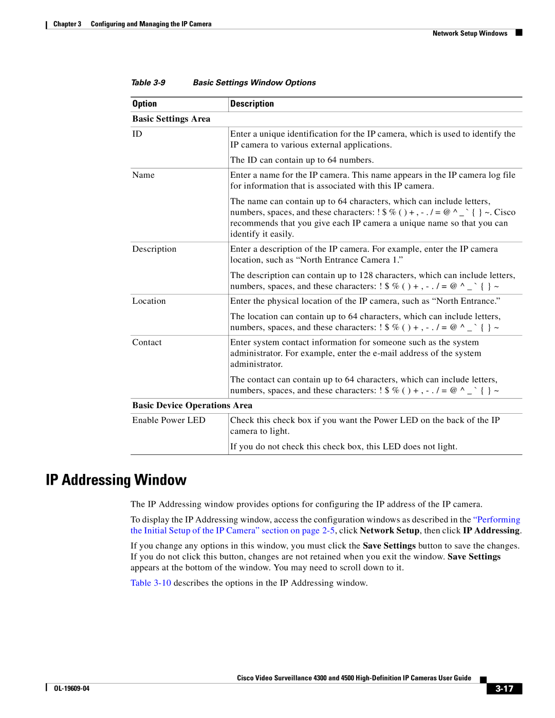
Table | Basic Settings Window Options | |
|
|
|
Option |
| Description |
|
| |
Basic Settings Area | ||
|
|
|
ID |
| Enter a unique identification for the IP camera, which is used to identify the |
|
| IP camera to various external applications. |
|
| The ID can contain up to 64 numbers. |
|
|
|
Name |
| Enter a name for the IP camera. This name appears in the IP camera log file |
|
| for information that is associated with this IP camera. |
|
| The name can contain up to 64 characters, which can include letters, |
|
| numbers, spaces, and these characters: ! $ % ( ) + , |
|
| recommends that you give each IP camera a unique name so that you can |
|
| identify it easily. |
|
|
|
Description |
| Enter a description of the IP camera. For example, enter the IP camera |
|
| location, such as “North Entrance Camera 1.” |
|
| The description can contain up to 128 characters, which can include letters, |
|
| numbers, spaces, and these characters: ! $ % ( ) + , |
|
|
|
Location |
| Enter the physical location of the IP camera, such as “North Entrance.” |
|
| The location can contain up to 64 characters, which can include letters, |
|
| numbers, spaces, and these characters: ! $ % ( ) + , |
|
|
|
Contact |
| Enter system contact information for someone such as the system |
|
| administrator. For example, enter the |
|
| administrator. |
|
| The contact can contain up to 64 characters, which can include letters, |
|
| numbers, spaces, and these characters: ! $ % ( ) + , |
|
|
|
Basic Device Operations Area
Enable Power LED
Check this check box if you want the Power LED on the back of the IP camera to light.
If you do not check this check box, this LED does not light.
IP Addressing Window
The IP Addressing window provides options for configuring the IP address of the IP camera.
To display the IP Addressing window, access the configuration windows as described in the “Performing the Initial Setup of the IP Camera” section on page
If you change any options in this window, you must click the Save Settings button to save the changes. If you do not click this button, changes are not retained when you exit the window. Save Settings appears at the bottom of the window. You may need to scroll down to it.
Table
|
| Cisco Video Surveillance 4300 and 4500 |
|
| |
|
|
| |||
|
|
|
| ||
|
|
|
| ||