Customer Order Number DOC-7813983= Text Part Number
Corporate Headquarters
Copyright 2002 Cisco Systems, Inc All rights reserved
Limitations and Restrictions First-Time Configuration
Software Features
About This Guide
Audience
Saving Configuration Changes
Using the Setup Command Facility
Configuring PIM
Configuring PPP Multiplexing
Where to Go Next
Configuring Redundancy
Mode y-cable
Assigning a QoS Boilerplate to an Interface
Page
Audience
Objectives
Organization
Chapter Title Description
Convention Description
Document Conventions
Boldface font
Boldface screen
Related Documentation
Additional Information
Obtaining Documentation
World Wide Web
Documentation CD-ROM
Obtaining Technical Assistance
Ordering Documentation
Documentation Feedback
Cisco.com
To access Cisco.com, go to the following website
Technical Assistance Center
Contacting TAC by Telephone
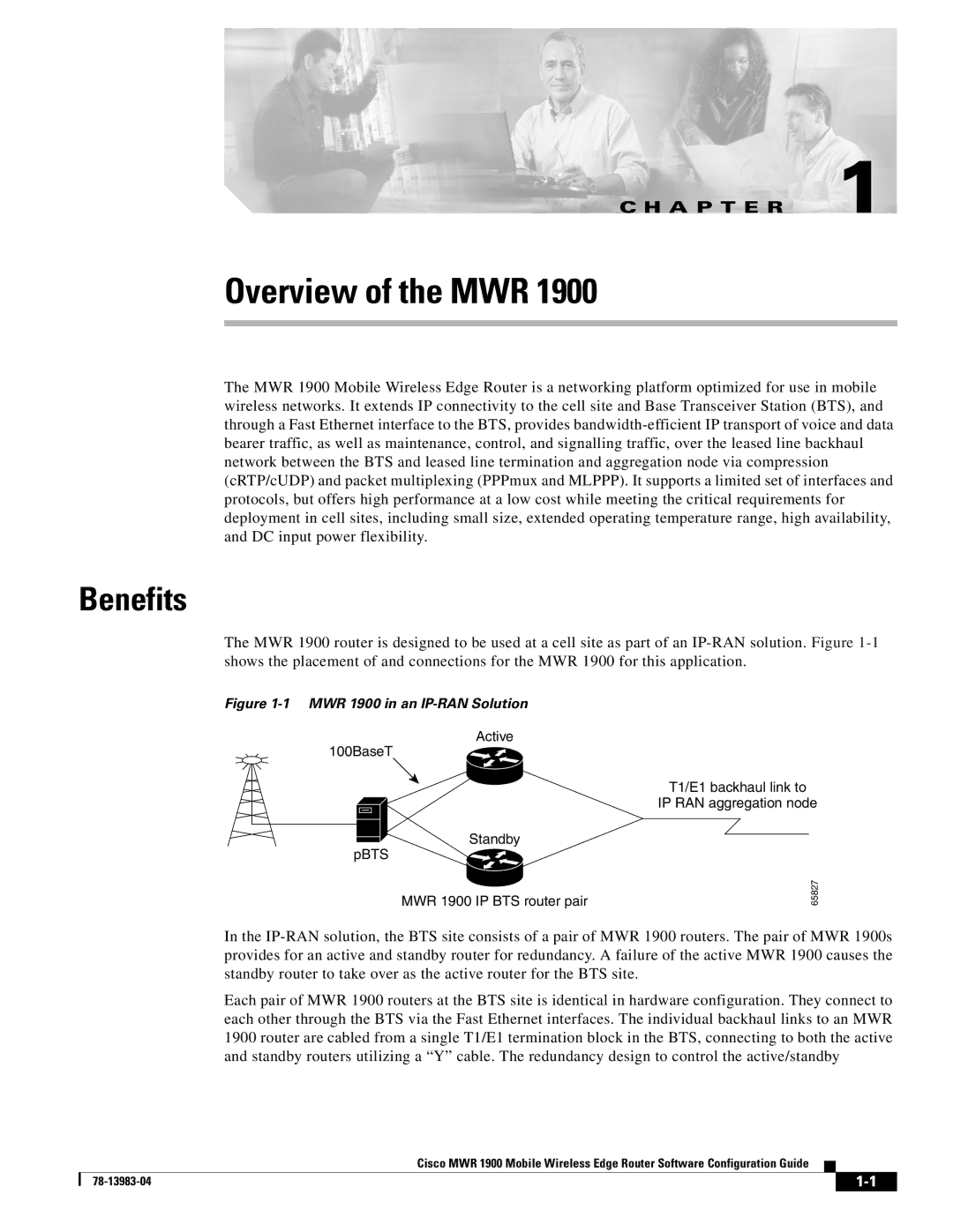
Benefits
Overview of the MWR
Cisco IOS Software
Software Features
Network Processor Software
MLP, PPP Control Path IPCP, NCP, LCP, Clns
RTP/UDP Header Compression
PPP Multiplexing/Demultiplexing
RTP Header Compression
Redundancy Support
MWR 1900 supports the following MIBs
MIB Support
RFC1213-MIB
RFC1253-MIB
802.1Q VLANs Frame Relay FR
Limitations and Restrictions
Before You Begin
Understanding Boot Images
Understanding Interface Numbering
Interface type Slot number/Interface number
Configuring Global Parameters
Using the Setup Command Facility
Before Starting Your Router
Enter a host name for the router this example uses
Viewing the configuration
You are then prompted to configure the specified interface
Completing the Configuration
Summary of interfaces is displayed
First-Time Configuration Where to Go Next
Where to Go Next
Getting Help
Cisco IOS Software Basics
Configure terminal
Understanding Command Modes
Exit , or logout
As interface serial 0/0
Saving Configuration Changes
Undoing a Command or Feature
Page
Configuring with the Command-Line Interface
Enter global configuration mode
Configuring the Host Name and Password
Prompt changes to Routerconfig#
Verifying the Version of Cisco IOS Software
Exit to global configuration mode
Configuring Loopback Interfaces
Exit interface configuration mode
Change the name of the router to a meaningful name
Configuring the FE Interface IP Address
Configuring Fast Ethernet Interfaces
Setting the Speed and Duplex Mode
Configuring PIM
Configuring Routing Protocol Attributes
Specify the speed
Configuring Hsrp Support
Enabling the FE Interface
Configuring Multilink Interfaces
Specify a priority
Configuring IP Address Assignment
Configuring Multilink PPP
Enable multilink PPP operation
Configuring RTP/UDP Compression
Configuring PPP Multiplexing
To set the default PPP protocol ID, enter
To set the maximum length of the subframe, enter
RPM-3config-if#ip rtp header-compression
Configuring T1 Interfaces
Configuring T1 and E1 Interfaces
Set the carrier delay for the serial interface
Configuring E1 Interfaces
Configuring QoS Attributes
Creating a Policy Map
Creating a Class Map
78-13983-04
Assigning a QoS Boilerplate to an Interface
Configuring Redundancy
Redundant MWR 1900s
Stand-Alone MWR
Exit y-mode configuration mode
Specify the interface to be used for backhauling
MWR1900-1#show running-config
Verifying the Configuration
Match access-group
Ip ospf message-digest-key 1 md5 mymd5pw
Ip ospf Hello-interval Ospf Dead-interval
Monitoring and Managing the MWR
Command Purpose
Show Commands for Monitoring the MWR
Show interface type slot / port
Show controllers
Show protocols
Command Reference
Clear ip rtp header-compression
Related Commands Description
Command Modes Command History Usage Guidelines Examples
Clear ppp mux
Clear ppp mux interface interface
Connections Interface configuration
Syntax Description Defaults Command Modes
Ip rtp header-compressionEnables RTP header compression
Ip rtp compression-connections
Ip rtp header-compression
Syntax Description Defaults Command Modes Command History
Passive
Related Commands Description
Mode y-cable
Mode y-cable
Standalone
Standby use-interface
Ppp mux
Command Modes Command History
Ppp mux delay integer no ppp mux delay
Ppp mux delay
Usage Guidelines Examples Related Commands
Default maximum length is Interface configuration
Defaults Command Modes Command History
Ppp mux frame
Ppp mux frame integer no ppp mux frame
Ppp mux pid integer
Ppp mux pid
Ppp mux subframe length integer No ppp mux subframe length
Ppp mux subframe length
Ppp mux subframe count
Default maximum is Interface configuration
Ppp mux subframe count integer No ppp mux subframe count
Following example enables redundancy mode
Global configuration
Invoked y-cable mode
Redundancy
Show ip rtp header-compression type number detail
Show ip rtp header-compression
1describes the significant fields shown in the display
Field Description
That can exist on an interface
Interface interface
Show ppp mux
2describes the significant fields shown in the display
Ppp mux Enables PPP multiplexing/demultiplexing
Show redundancy
This command has no attributes
Invokes redundancy mode
Invokes y-cable mode
Stand-alone configuration
Standby
Cable configuration
Syntax Description Defaults
Standalone
No standalone
Standby use-interface interface health revertive backhaul
Standby use-interface
Standby use-interface loopback102 revertive
Page
IP address
Cisco IOS About Command modes Enable mode
Counters, PPP multiplexing
IN-2
MIB support Mode y-cable
Configuring
Command
IN-4