Chapter 1 Product Overview
Cisco uBR7100 Series Routers Physical Description
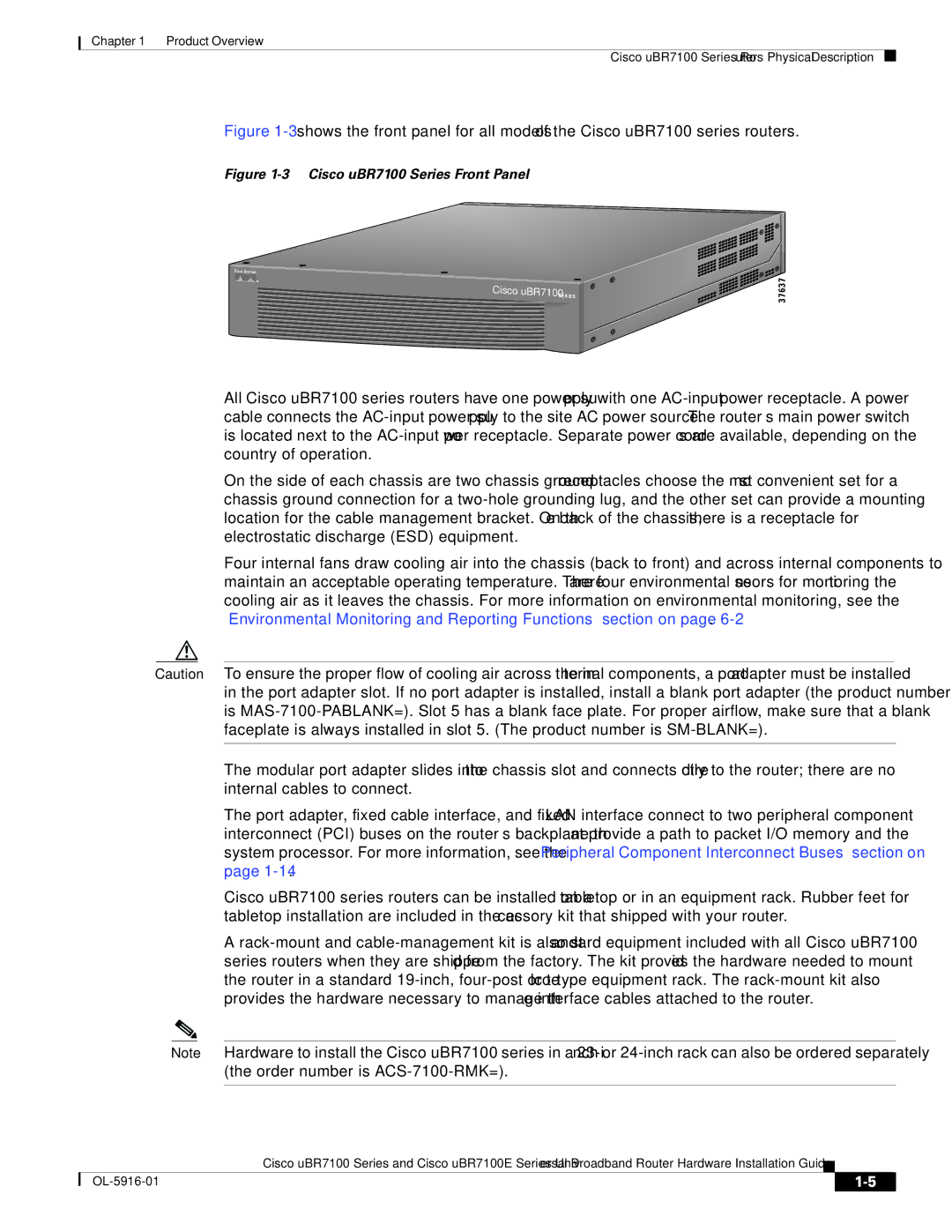
Figure 1-3 shows the front panel for all models of the Cisco uBR7100 series routers.
Figure 1-3 Cisco uBR7100 Series Front Panel
Cisco
uBR7100 | SERIES |

![]()
![]()
![]()
![]()
![]()
![]()
![]()
![]() 37637
37637
All Cisco uBR7100 series routers have one power supply with one
On the side of each chassis are two chassis ground
Four internal fans draw cooling air into the chassis (back to front) and across internal components to maintain an acceptable operating temperature. There are four environmental sensors for monitoring the cooling air as it leaves the chassis. For more information on environmental monitoring, see the “Environmental Monitoring and Reporting Functions” section on page
Caution To ensure the proper flow of cooling air across the internal components, a port adapter must be installed in the port adapter slot. If no port adapter is installed, install a blank port adapter (the product number is
The modular port adapter slides into the chassis slot and connects directly to the router; there are no internal cables to connect.
The port adapter, fixed cable interface, and fixed LAN interface connect to two peripheral component interconnect (PCI) buses on the router’s backplane that provide a path to packet I/O memory and the system processor. For more information, see the “Peripheral Component Interconnect Buses” section on page
Cisco uBR7100 series routers can be installed on a tabletop or in an equipment rack. Rubber feet for tabletop installation are included in the accessory kit that shipped with your router.
A
Note Hardware to install the Cisco uBR7100 series in a
Cisco uBR7100 Series and Cisco uBR7100E Series Universal Broadband Router Hardware Installation Guide
|
| ||
|
|